
引 言
磁浮列车是一个集机械、控制、电力电子等于一体的系统,间隙传感器测量电磁铁与轨道间的相对间隙、加速度传感器测量电磁铁的垂向加速度,通过加速度信号积分得到电磁铁的速度信号.控制系统接受传感器信号,根据控制算法计算得到控制信号,将信号通过执行部件施加到电磁铁,通过调整电磁铁的电压或电流而调整电磁力,使得电磁铁稳定悬浮于轨道下方.在信号的测量和接收、信号处理和信号输出和执行环节,时滞是不可避免的.如间隙和加速度传感器信号在进入控制器之前需进行低通滤波,加速度信号在进行积分计算速度之前需进行高通滤波以消除重力加速度的影响,信号积分和转换的过程就会使得信号发生延时;滤波和转换后的信号需要根据控制算法进行逻辑运算,得到控制量并输出,信号的逻辑运算环节也会产生时滞.时滞的存在会引起磁浮系统动力学行为的改变,甚至会导致系统失稳.国防科大的磁浮实验车在试验过程中就曾出现因为控制环节时滞过大而导致剧烈的车轨共振[15],同济大学也开展了实车测试,实验表明间隙反馈时滞为0.027 s时车轨振动剧烈[16].在其他工程应用中,亦有很多例子表明,时滞会导致系统发生共振、分岔等复杂动力学行为[17-19].本文关注时滞对磁浮车辆车轨耦合系统的影响具有实际工程意义和必要性.
针对时滞对磁浮车辆稳定性的影响,李金辉等[20]分析了时间延时对车轨耦合系统稳定性的影响,分析表明,间隙和速度通道的时间延时会减弱稳定性,应尽量避免,而电流通道的延时有益于系统稳定性.王洪坡等[21-23]分别考虑考虑位置反馈控制时滞和速度反馈控制时滞的磁浮系统的Hopf分岔和共振问题,将时滞作为Hopf分岔条件,分析表明,当时间延时超过一定大小后会发生Hopf分岔.还研究了周期解与导轨激励和控制参数之间的关系.数值结果显示,合适的选取时间延时和控制参数,可以很好的抑制非共振响应.张玲玲等[24-28]运用中心流形和正规型理论,讨论了具有间隙反馈控制时滞和速度反馈控制时滞的刚性轨道磁浮列车以及弹性轨道磁浮列车的稳定性和Hopf分岔.采用Pseudo-Oscillator分析的摄动方法来得到Hopf分岔引起的周期解的振幅近似表达式[29],并验证了其有效性,分析了影响系统稳定性的时滞和速度反馈控制增益的变化关系.徐俊起等[16]研究了同时考虑位置反馈时滞和速度反馈时滞时的车轨耦合系统Hopf分岔问题,绘制了分岔图,通过数值分析和实车实验验证了理论分析的有效性.
以上研究证明了控制环节时滞对磁浮列车稳定性有重要影响,当时滞超过一定数值时系统会发生Hopf分岔,即存在一临界时滞.然而,研究均基于单电磁铁悬浮模型,与整车系统相差较远,且时滞临界值与车辆系统参数的关系研究仍然太少,如车辆运行速度、反馈控制增益、悬挂参数以及导轨柔性等.
本文考虑间隙反馈控制环节的时间滞后,建立了磁浮车辆轨道耦合动力学模型,数值积分求解系统振动控制方程,编写数值仿真程序开展计算,通过判断系统在不同时滞条件下的振幅变化情况确定临界时滞.基于此,研究了临界时滞与车辆运动速度、反馈控制增益系数、悬挂参数和导轨参数的关系,以期为增强磁浮列车在时滞条件下的稳定性提供设计参考.
1 车轨耦合模型
1.1 模型概述
典型磁浮车辆由4个完全相同的磁浮架连接而成,每个磁浮架由两个相同的模块组成,每个模块上由4个电磁铁和一个推进电机组成,具有独立悬浮、导向与推进功能.
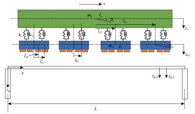
将车辆结构简化为一个刚性车体和4个刚性磁浮架,重心与几何中心重合,每个磁浮架上有4个电磁铁.如此简化可得到10自由度车辆动力学模型,分别是车体沉浮$z_{\rm c}$和点头$\theta$$_{\rm c}$,磁浮架的沉浮$z_{{\rm b}i}$和点头$\theta$$_{{\rm b}i}(i$=1, 2, 3, 4).将磁浮车辆的导轨模拟为一系列简支Bernoulli-Euler梁.常导磁浮车轨耦合模型如图1所示. 图中$m_{\rm c}$车体质量;$I_{\rm c}$车体点头运动方向的转动惯量;$m_{\rm b}$磁浮架质量;$I_{\rm b}$磁浮架点头运动方向的转动惯量;$k_{\rm s}$二系悬挂刚度;$c_{\rm s}$二系悬挂阻尼;$L$悬跨长度;v车辆运动速度;$ l_{{\rm c}j }(j$=1, 2, 3, 4)车体中心到第$j$个磁浮架中心的距离;$l_{{\rm b}i }(i$=1, 2)磁浮架中心到第i个减震器的距离;$l_{{\rm e}k }(k$=1, 2, 3, 4)磁浮架中心到第k个电磁铁中心的距离.
图1
1.2 车辆振动方程
车体振动方程如下
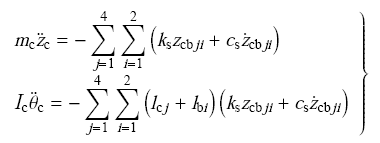
磁浮架振动方程如下
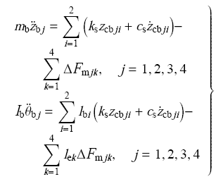
其中, $\Delta$F$_{{\rm m}jk}$是指第$j$个磁浮架上的第k个电磁铁的电磁力变化.方程中,二系悬挂变化量与速度表示为
1.3 导轨振动方程
将导轨模拟为一系列简支梁,采用模态叠加法得到导轨梁的运动方程. 承载磁浮车辆的第M根导轨简支梁的振动方程可表示为
边界条件为
当车辆行驶在导轨上时,由车辆作用于导轨上的力表示为
式(6)中,$x_{jk}$是第$j$个磁浮架上第k个电磁铁在第M个导轨梁上的位置,$t_{jk}$是第$j$个磁浮架上第k电磁铁进入第M根导轨梁的时间,$F_{{\rm m}jk}$是指第$j$个磁浮架上的第k个电磁铁的电磁力
$\delta$($ \cdot )$是Dirac函数
$H(t)$是单位阶跃函数
基于模态叠加方法,导轨简支梁的挠曲可以表示为
式中,$q_{n}(t)$是与第M根导轨简支梁的第$n$阶模态相关的广义坐标,是下式的解
式中,$\zeta$$_{n}$是阻尼比,$\omega$$_{n}$是第$n$阶模态的固有频率.
1.4 电磁力
第$j$个磁浮架上的第k个电磁铁的悬浮力计算式为
式中,$A_{\rm m}$是磁极面积,$N_{\rm m}$是电磁铁线圈匝数,$\mu$0为空气磁导率,$I_{0}$为初始静态平衡位置电流,$\delta$0为初始平台平衡位置间隙,$i_{jk}$和$s_{jk}$是车辆运行时电流和悬浮间隙的波动.
线性化电磁力可表示为
其中
$z_{{\rm g}jk}$是电磁铁位置处导轨梁的扰度,用下式计算
1.5 车轨耦合系统方程及求解
根据以上推导过程,车体振动方程(1)、磁浮架振动方程(2)、导轨振动方程(11)以及电磁力计算式(15)构成了车辆轨道垂向耦合动力学方程,方程降阶可写为如下形式
采用四阶Runge-Kutta法对式(18)进行直接积分,得到耦合系统在时域内的响应.依据此编写了计算程序开展计算.
2 时滞在计算过程中处理方法
磁浮控制系统的每个环节均存在时滞,而为方便分析,本文假设所有的时滞都发生在控制环节.此外,本文只考虑间隙反馈控制环节产生的时滞,暂不考虑速度反馈控制中的时滞.采用比例微分(PD)控制算法,根据悬浮间隙变化量和悬浮间隙变化速度对电流进行反馈控制,以此调整电磁力实现稳定悬浮.电流反馈控制表示为
式中,$k_{\rm p}$,$k_{\rm d}$分别是电磁铁悬浮气隙和速度的反馈控制增益,$\tau$$_{\rm p}$是间隙反馈时滞,$s_{jk}$车辆运行时悬浮间隙的波动,$\dot {z}_{jk}$是电磁铁的垂向速度
计算程序中,采用$t$$-$$\tau$$_{\rm p}$时刻的悬浮间隙波动,如式(20),依据式(19)来计算控制电流,以此体现时间滞后对磁浮车辆-导轨系统振动的影响.
3 结果分析
3.1 设计参数
表1 车体结构参数
Table 1
| mc/kg | ,c/(kg.m2) | mb/kg | Ib/(kg.m2) |
|---|---|---|---|
| 29200 | 1401600 | 8000 | 6500 |
| ks/(N.m-1) | Cs/(Ns.m-1) | (lc1,-lc4)/m | (lc2,-lc3)/m |
| 8.515X10⁴ | 1.058X10⁴ | 9 | 3 |
| lb1 /m | lb2/m | (le1,-le4)/m | (le2,-le3)/m |
| 1.5 | -1.5 | 2.25 | 0.75 |
表2 轨道结构参数
Table 2
| L/m | Nmode | mg/(kg.m-1) | E"(N.m-1) | Zn |
|---|---|---|---|---|
| 25 | 12 | 3760 | 2.456X10¹⁰ | 0.05 |
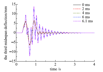
3.2 临界时滞确定方法
图2
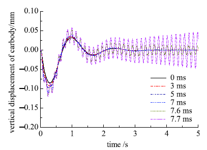
图3
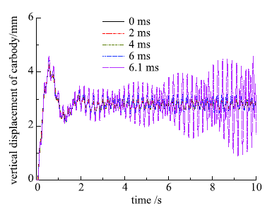
图4
3.3 参数影响规律
图5给出了间隙反馈控制增益$k_{\rm p}$与临界时滞关系曲线.图中,分别计算了采用刚性导轨模型,以及采用柔性导轨模型在600 km/h, 400 km/h, 200 km/h和静止在原地情况下的临界时滞与$k_{\rm p}$的关系曲线. 结果很明显,临界时滞随$k_{\rm p}$增大逐渐减小,但$k_{\rm p}$越大,临界时滞减小速率越慢,最后趋于定值.当时滞存在时,采用刚性轨道的车辆稳定性优于柔性轨道.分析还表明,当导轨考虑为刚性时,临界时滞与车辆运行速度无关;导轨考虑为柔性时,车速越高临界时滞越大,结果越趋向于刚性轨道;车辆在原地静止时,临界时滞越小,表明考虑时滞时,稳定性最差,更容易发生失稳.
图5
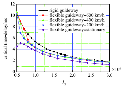
图5
间隙反馈控制增益与临界时滞关系曲线
Fig.5
Relationship between the critical time delay with clearance feedback control gain
图6是速度反馈控制增益$k_{\rm d}$与临界时滞关系曲线.结果也显示,当间隙反馈时滞存在时,采用刚性导轨磁浮车辆的稳定性性能优于柔性轨道.随着$k_{\rm d}$的增大,临界时滞逐渐增大. 在车辆运行时,随着$k_{\rm d}$增大,临界时滞逐渐与刚性导轨情况一致,且速度越高,越快趋向于一致.车辆静止时的稳定性依然 最差.
图6
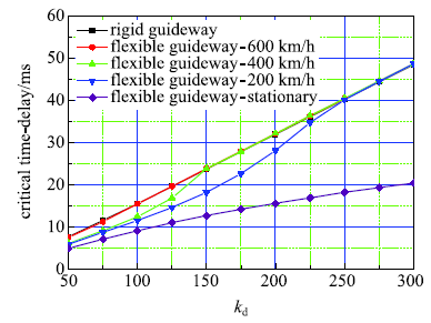
图6
速度反馈控制增益与临界时滞关系曲线
Fig.6
Relationship between the critical time delay with velocity feedback control gain
图7
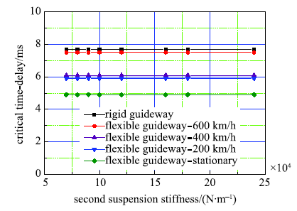
图7
二系悬挂刚度与临界时滞关系曲线
Fig.7
Relationship between the critical time delay with second suspension stiffness
图8
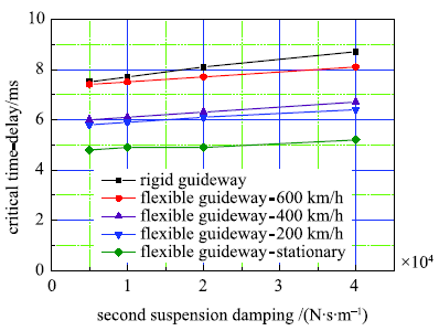
图8
二系悬挂阻尼与临界时滞关系曲线
Fig.8
Relationship between the critical time delay with second suspension damping
图9
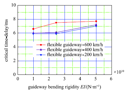
图9
导轨弯曲刚度与临界时滞关系曲线
Fig.9
Relationship between the critical time delay with guideway bending rigidity
图10
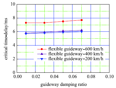
图10
导轨阻尼比与临界时滞关系曲线
Fig.10
Relationship between the critical time delay with guideway damping ratio
4 结 论
本文对考虑间隙反馈控制环节时滞的磁浮车辆系统稳定性进行了数值仿真分析,研究了临界时滞与车辆运行速度、反馈控制增益系数、悬挂系数和导轨参数的关系.为提高磁浮车辆在间隙反馈时滞条件下的稳定性,增强磁浮列车安全性,可考虑以下方法:
(1)增大导轨弯曲刚度和阻尼比;
(2)减小间隙反馈控制增益;
(3)增大速度反馈控制增益;
(4)增大二系悬挂阻尼.
此外,鉴于运行情况下磁浮车辆的临界时滞总是大于车辆静止情况,因此,应将车辆在静止状态下的临界时滞作为安全限值应用于系统设计.
参考文献
Review of maglev train technologies

This paper reviews and summarizes Maglev train technologies from an electrical engineering point of view and assimilates the results of works over the past three decades carried out all over the world. Many researches and developments concerning the Maglev train have been accomplished; however, they are not always easy to understand. The purpose of this paper is to make the Maglev train technologies clear at a glance. Included are general understandings, technologies, and worldwide practical projects. Further research needs are also addressed.
磁浮车辆/轨道系统动力学(I)-磁轨相互作用及稳定性
磁浮车辆/轨道系统动力学问题直接影响磁浮交通的安全性、舒适性和经济性,而这三个性能则是决定其应用前景的重要因素。作为系列文章的第一部分,论述了磁浮系统动力学研究中最基本和最关键的问题——磁/轨相互作用及磁浮系统稳定性。关于磁/轨相互作用研究,目前在电磁铁二维受力理论分析、数值求解及其动态特性研究方面取得了显著的进展,而三维磁/轨作用理论分析与试验研究是其未来的研究方向。磁浮系统稳定性研究由单纯的悬浮稳定性研究、单铁/轨道系统稳定性研究逐步进入磁浮车辆/轨道系统稳定性研究,将来的研究仍需探索新的磁浮系统稳定性分析方法,并结合工程实际开展磁浮列车系统动力稳定性应用研究。
Dynamics of maglev vehicle/guideway systems (I)-magnet/rail interaction and system stability
磁浮车辆/轨道系统动力学问题直接影响磁浮交通的安全性、舒适性和经济性,而这三个性能则是决定其应用前景的重要因素。作为系列文章的第一部分,论述了磁浮系统动力学研究中最基本和最关键的问题——磁/轨相互作用及磁浮系统稳定性。关于磁/轨相互作用研究,目前在电磁铁二维受力理论分析、数值求解及其动态特性研究方面取得了显著的进展,而三维磁/轨作用理论分析与试验研究是其未来的研究方向。磁浮系统稳定性研究由单纯的悬浮稳定性研究、单铁/轨道系统稳定性研究逐步进入磁浮车辆/轨道系统稳定性研究,将来的研究仍需探索新的磁浮系统稳定性分析方法,并结合工程实际开展磁浮列车系统动力稳定性应用研究。
随机不平顺激励下磁浮车辆轨道梁动力响应
建立了高速常导磁浮交通车辆轨道梁空间耦合模型,探讨了合理的磁浮线路功率谱形式,利用分离迭代的数值积分方法求解了大规模非线性耦合动力方程. 利用计算结果分析了随机不平顺对系统动力学指标影响规律,并采用功率谱密度曲线进行了谱分析,得到了高速磁浮交通车梁耦合系统随机振动的基本规律.
Dynamic response of maglev vehicle track beam under random irregularity
建立了高速常导磁浮交通车辆轨道梁空间耦合模型,探讨了合理的磁浮线路功率谱形式,利用分离迭代的数值积分方法求解了大规模非线性耦合动力方程. 利用计算结果分析了随机不平顺对系统动力学指标影响规律,并采用功率谱密度曲线进行了谱分析,得到了高速磁浮交通车梁耦合系统随机振动的基本规律.
Maglev vehicle guideway vertical random response and ride quality
Summary The research and development (R & D) of maglev technology had made a great progress in China since the early 1980s. Especially, a 35 km-long Shanghai high-speed maglev railway employing the German Transrapid system began to be constructed on March 1, 2001. Based on the Transrapid system, the paper develops a 10-degree-of-freedom model of maglev vehicle running over three types of guideways with constant speed. Random guideway irregularities are discussed and taken into account for simulation of the vehicle response and for evaluation of the ride comfort. Using the direct time integration method and the discrete fast Fourier transform (DFFT), random responses of the maglev vehicle-guideway systems are obtained and analyzed. Numerical results show that the resonant frequency of car body acceleration response is 0.5 1 Hz, and there is a 2.2 Hz periodic vibration due to the periodic configuration of rigid piers when the maglev vehicle travels over the elevated-beam guideway. The car body acceleration power spectral density (PSD) curves meet well the ride quality criterion of the urban tracked aircushion vehicle (UTACV) and the maximum acceleration of car body is less than 0.05 g. Moreover, the Sperling ride index values are less than 2.5 as long as the operational speed is less than 450 km/h. It is concluded that the maglev vehicle ride quality is quite well.
Motion stability of high-speed maglev systems in consideration of aerodynamic effect: A study of a single magnetic suspension system
In this study, the intrinsic mechanism of aerodynamic effects on the motion stability of a high-speed maglev system was investigated. The concept of a critical speed for maglev vehicles considering the aerodynamic effect is proposed. The study was carried out based on a single magnetic suspension system, which is convenient for proposing relevant concepts and obtaining explicit expressions. This study shows that the motion stability of the suspension system is closely related to the vehicle speed when aerodynamic effects are considered. With increases of the vehicle speed, the stability behavior of the system changes. At a certain vehicle speed,the stability of the system reaches a critical state, followed by instability. The speed corresponding to the critical state is the critical speed. Analysis reveals that when the system reaches the critical state, it takes two forms, with two critical speeds, and thus two expressions for the critical speed are obtained. The conditions of the existence of the critical speed were determined, and the effects of the control parameters and the lift coefficient on the critical speed were analyzed by numerical analysis. The results show that the first critical speed appears when the aerodynamic force is upward,and the second critical speed appears when the aerodynamic force is downward. Moreover, both critical speeds decrease with the increase of the lift coefficient.
Effects of guideway's vibration characteristics on the dynamics of a maglev vehicle
The levitation control system in an electromagnetically levitated vehicle controls the voltage in its winding to maintain the air gap, which is the clearance between the electromagnet and the guideway, within an allowable range of variation, while strongly interacting with the flexible guideway. Thus, the vibrational characteristics of the guideway play an important role in the dynamics of Maglev (magnetically levitated) vehicles that utilise an active electromagnetic suspension system. In this study, the effects of the guideway''s vibrational characteristics, such as natural frequency and damping, on the dynamics of the Maglev vehicle UTM-02 are numerically and experimentally analysed. From these analyses, the coupled equations of motion of the simplified vehicle guideway model with three degrees of freedom are derived. Eigenvalues are calculated and frequency response analysis is also performed, in order to obtain a clear understanding of the dynamic characteristics resulting from the guideway''s vibrational characteristics. To verify the numerical results, air gap tests of the urban Maglev vehicle UTM-02 are also carried out. These results lead us to recommend that the natural frequency of the guideway be decreased by increasing mass density rather than by decreasing rigidity, and that its damping ratio be increased in the Maglev vehicle UTM-02 employing a five-state feedback control law as a levitation control law.
Prediction of ride quality of a Maglev vehicle using a full vehicle multi-body dynamic model
In magnetically levitated (Maglev) transportation systems, especially in electromagnetic suspension system (EMS) type Maglev systems, highly accurate prediction of ride quality is very important in order to reasonably relax guideway construction tolerances or constraints and stiffness while meeting the specification for ride comfort, thereby reducing guideway construction and maintenance costs. A full vehicle multi-body dynamic model is proposed, to facilitate a rigorous ride quality prediction of an EMS-type Maglev vehicle. Using the more realistic dynamic model proposed in this paper, the effects of guideway deflection limits, surface roughness, and levitation control system parameters on ride quality are studied numerically. The results obtained from the simulation studies are then used to facilitate a discussion of the trade-off between guideway smoothness and vehicle suspension. It can be expected that these studies could suggest cost-effective specifications for guideway construction tolerances and stiffness and EMS.
Curving performance simulation of an EMS-type maglev vehicle
For electromagnetic suspension (EMS) type urban Maglev vehicles using a U-shaped electromagnet, the levitation and guidance forces are generated by only one electromagnet. Although the levitation force is actively controlled by changing the voltage of the electromagnet, the guidance force is passively determined by the levitation force. In addition, the curve negotiation performance of EMS-type urban Maglev vehicles using a U-shaped electromagnet must be considered, because an urban guideway may have some curves with shorter radii. It is, therefore, necessary to predict the curving performance with the greatest accuracy possible, in order to improve electromagnetic suspension and establish guideway design specifications. The objective is to establish a new dynamic modelling technique, so as to achieve more realistic curving simulation and thus to more accurately evaluate the curving performance of an EMS-type Maglev vehicle. The use of a full vehicle multibody dynamic model is proposed, and is applied to the evaluation of curving performance. Design changes are also investigated to obtain the bogie design directions for minimising variation in the lateral air gap, which is a criterion for curving performance.
A parametric study on the dynamics of urban transit maglev vehicle running on flexible guideway bridges
The purpose of this study is to develop a numerical model for a dynamic interaction analysis of an actively controlled maglev vehicle and flexible guideway structure. In addition, an investigation is performed of the effect of vehicle and guideway characteristics on dynamic responses of low and medium speed maglev systems. Dynamic governing equations are derived by combining the 5-dof maglev vehicle model, the modal properties of guideway structures and a LQG controller for electromagnetic suspension. An investigation is then carried out on the effect of vehicle models, vehicle speed, irregularity, guideway deflection ratio, span length, span continuity and damping ratio on dynamic responses of the relatively low speed maglev vehicle and guideway structures. From the numerical simulation, it is found that the air gap of the vehicle is strongly affected by vehicle speed, tract roughness and guideway deflection ratio. In particular, the guideway deflection ratio is the most influential parameter which governs the air gap. Continuous span girders are found to be effective in reducing the air gap because of its smooth curvature and small deflection slope near the support. However, the span length and damping ratio of the guideway structure do not affect the air gap. The overall dynamic magnification factor of the guideway girder is not severe compared to the traditional wheel type vehicle.
Coupled vibration analysis of Maglev vehicle-guideway while standing still or moving at low speeds
Dynamic instability, that is, resonance, may occur on an electromagnetic suspension-type Maglev that runs over the elevated guideway, particularly at very low speeds, due to the flexibility of the guideway. An analysis of the dynamic interaction between the vehicle and guideway is required at the design stage to investigate such instability, setting slender guideway in design direction for reducing construction costs. In addition, it is essential to design an effective control algorithm to solve the problem of instability. In this article, a more detailed model for the dynamic interaction of vehicle/guideway is proposed. The proposed model incorporates a 3D full vehicle model based on virtual prototyping, flexible guideway by a modal superposition method and levitation electromagnets including feedback controller into an integrated model. By applying the proposed model to an urban Maglev vehicle newly developed for commercial application, an analysis of the instability phenomenon and an investigation of air gap control performance are carried out through a simulation.
Suppression of maglev vehicle-girder self-excited vibration using a virtual tuned mass damper
The self-excited vibration that occurs between a stationary Electromagnetic Suspension (EMS) maglev vehicle and a girder is a practical problem that greatly degrades the performance of a maglev system. As of today, this problem has not been fully solved. In this article, the principle underlying the self-excited vibration problem is explored, and it is found that the fundamental resonance frequency of the maglev girder plays a vital role in the initiation of the self-excited vibration. To suppress the self-excited vibration, a scheme applying a tuned mass damper (TMD) to the maglev girder is proposed, and the stability of the combined system is analyzed. Furthermore, a novel concept of a virtual TMD is introduced, which uses an electromagnetic force to emulate the force of a real TMD acting on the girder. However, in the presence of the time delay caused by the inductance of the electromagnets, the stability analysis of the levitation system combined with the virtual TMD becomes complex. Analysis of the stability shows that there exist some repeated time delay zones within which the overall system is stable. Based on this rule, time delay control is introduced to stabilize the system with a virtual TMD, and a procedure to determine the optimal time delay and gain is proposed. Numerical simulation indicates that the proposed virtual TMD scheme can significantly suppress the self-excited vibration caused by one unstable vibration mode, and is suitable for application to EMS maglev systems.
Application of least mean square algorithm to suppression of maglev track-induced self-excited vibration
78 We construct the maglev electromagnet–track coupled model and examine its stability. 78 We employ the harmonic balance method to investigate the amplitude of the vibration. 78 An adaptive LMS algorithm with phase correction is employed to cancel the vibration. 78 The analysis shows that the presented algorithm can totally eliminate the vibration. 78 The presented algorithm is validated by numerical simulation and experiments.
Amplitude control of the track-induced self-excited vibration for a maglev system
61This paper investigates the principle of the track-induced self-excited vibration.61The amplitude of the vibration is investigated using the harmonic balance method.61We discover that the amplitude of the vibration is mainly decided by the voltage of the power supplier.61We provide a simple scheme to suppress the track-induced self-excited vibration.
The active control of maglev stationary self-excited vibration with a virtual energy harvester
This paper addresses the active control of stationary self-excited vibration, which degrades the stability of the levitation control, decreases the ride comfort, and restricts the construction cost of the maglev system. First, a minimum interaction model containing a flexible bridge and a single levitation unit is presented. Based on the minimum interaction model, the principle underlying the self-excited vibration is explored. It shows that the active property of the levitation system is the root of self-excited vibration. Consider that the energy of vibration may be absorbed by the electromagnetic energy harvester (EEH), so that a technique applying it to the bridge is proposed, and the stability of the combined system is analyzed. However, its hardware structure is complicated, and the cost of construction is prohibitive. Then the novel conception of the virtual EEH is brought forward, which uses the electromagnetic force to emulate the force of a real energy harvester acting on the bridge. With the estimation of the vertical velocity of the bridge and the frequency of vibration, the self-oscillatory is avoided as well by adding an extra control instruction to the electromagnet. After building the overall dynamic model with details, numerical simulations and field experiments are carried out, and the results illustrating the improvement of stability are provided and analyzed.
Nonlinear dynamic analysis on maglev train system with flexible guideway and double time-delay feedback control
时滞耦合系统非线性动力学的研究进展
随着对自然界客观规律的深入认识,工程系统设计的精细化和复杂性要求也与日剧增.在许多耦合的动态系统设计过程中要考虑由耦合过程的时滞所引发的动力学行为,该时滞来自于与传感系统、作动系统和控制系统耦合的过程.耦合时滞也广泛存在于交通、系统生物学、电子通讯、神经和信息网络等技术中.本文首先从耦合时滞出发,在以时滞为中心的耦合系统复杂动力学机制、时滞镇定耦合系统的实验基础和实现、快慢变时滞耦合系统动力学和时滞神经网络同步和去同步4个方面,对耦合时滞诱发的动力学研究进展进行综述.着重介绍了时滞耦合系统中耦合时滞诱发的高余维分岔奇异性及新的定量分析方法、中立型时滞微分方程的规范型计算、具有耦合时滞的非线性系统中耦合时滞和非线性参数的辨识方法与实验实现、快慢变时滞耦合系统的张弛振荡、耦合时滞诱发的网络系统的同步模式切换等问题的研究进展;然后在应用方面重点介绍了车床磨削加工过程中耦合时滞诱发的颤振及其机理、具有惯性项和耦合时滞的神经网络系统中耦合时滞诱发的高余维分岔和复杂动力学、时滞动力吸振器与隔振装置的设计与实验实现.最后,从耦合时滞系统的一般性理论和工程应用两个方面展望了近期值得关注的一些问题.
Review on nonlinear dynamics in system with coupling delays
随着对自然界客观规律的深入认识,工程系统设计的精细化和复杂性要求也与日剧增.在许多耦合的动态系统设计过程中要考虑由耦合过程的时滞所引发的动力学行为,该时滞来自于与传感系统、作动系统和控制系统耦合的过程.耦合时滞也广泛存在于交通、系统生物学、电子通讯、神经和信息网络等技术中.本文首先从耦合时滞出发,在以时滞为中心的耦合系统复杂动力学机制、时滞镇定耦合系统的实验基础和实现、快慢变时滞耦合系统动力学和时滞神经网络同步和去同步4个方面,对耦合时滞诱发的动力学研究进展进行综述.着重介绍了时滞耦合系统中耦合时滞诱发的高余维分岔奇异性及新的定量分析方法、中立型时滞微分方程的规范型计算、具有耦合时滞的非线性系统中耦合时滞和非线性参数的辨识方法与实验实现、快慢变时滞耦合系统的张弛振荡、耦合时滞诱发的网络系统的同步模式切换等问题的研究进展;然后在应用方面重点介绍了车床磨削加工过程中耦合时滞诱发的颤振及其机理、具有惯性项和耦合时滞的神经网络系统中耦合时滞诱发的高余维分岔和复杂动力学、时滞动力吸振器与隔振装置的设计与实验实现.最后,从耦合时滞系统的一般性理论和工程应用两个方面展望了近期值得关注的一些问题.
时变参数时滞减振控制研究
时滞动力吸振器对谐波激励有着良好的减振控制效果,但对随机激励的减振控制效果却并不明显,具体表现为时滞动力吸振器对随机激励的减振控制效果与被动吸振器几乎相同.针对上述问题,提出了一种新的时变参数时滞减振控制方法.在原有时滞减振控制方法的基础上,首先将时滞增益系数由定值形式变为时间函数形式,然后通过时变优化得到多组时滞控制参数并使其以一定时间周期循环作用于减振控制过程,通过这种方法进一步改善了时滞动力吸振器减振性能.最后以二自由度时滞动力吸振器减振模型为例,以主系统的振动响应为仿真对象,运用精细积分法求解了具有时变时滞参数的时滞动力学方程,以此得到了在谐波激励和随机激励作用下主系统振动的时域仿真结果.研究结果表明,在时变参数时滞动力吸振器的控制下,主系统无论是受谐波激励作用还是受随机激励作用,其振动位移、振动速度和振动加速度均比在定值参数时滞动力吸振器控制下时有大幅的减小,时滞动力吸振器的减振性能有了明显的改善.
The research of time delay vibration control with time-varying parameters
时滞动力吸振器对谐波激励有着良好的减振控制效果,但对随机激励的减振控制效果却并不明显,具体表现为时滞动力吸振器对随机激励的减振控制效果与被动吸振器几乎相同.针对上述问题,提出了一种新的时变参数时滞减振控制方法.在原有时滞减振控制方法的基础上,首先将时滞增益系数由定值形式变为时间函数形式,然后通过时变优化得到多组时滞控制参数并使其以一定时间周期循环作用于减振控制过程,通过这种方法进一步改善了时滞动力吸振器减振性能.最后以二自由度时滞动力吸振器减振模型为例,以主系统的振动响应为仿真对象,运用精细积分法求解了具有时变时滞参数的时滞动力学方程,以此得到了在谐波激励和随机激励作用下主系统振动的时域仿真结果.研究结果表明,在时变参数时滞动力吸振器的控制下,主系统无论是受谐波激励作用还是受随机激励作用,其振动位移、振动速度和振动加速度均比在定值参数时滞动力吸振器控制下时有大幅的减小,时滞动力吸振器的减振性能有了明显的改善.
含时滞反馈与涨落质量的记忆阻尼系统的随机共振
针对具有记忆效应的欠阻尼系统, 存在时滞反馈与涨落质量, 本文主要研究了其输出稳态响应振幅的随机共振效应. 首先通过引入新变量和运用小时滞近似展开理论, 将具有非马尔科夫特性的原系统转化为等价的两维马尔科夫线性系统, 再利用Shapiro-Loginov公式和Laplace变换获得了系统响应的一阶稳态矩和稳态响应振幅的解析表达式. 结果表明: 当系统参数满足Routh-Hurwitz稳定条件时, 稳态响应振幅随质量涨落噪声强度、周期驱动信号频率以及时滞的变化均存在随机共振现象, 其中随机多共振现象也被观察到. 在适当范围内, 通过控制时滞反馈, 系统的随机共振效应随着时滞的增大而增强, 而较长的记忆时间及增大阻尼参数均对共振行为呈现抑制作用.有效调控时滞反馈与记忆效应的变化关系将有助于增强系统对周期驱动信号的响应强度. 最后, 通过数值模拟计算验证了理论结果的有效性.
Stochastic resonance of a memorial-damped system with time delay feedback and fluctuating mass
针对具有记忆效应的欠阻尼系统, 存在时滞反馈与涨落质量, 本文主要研究了其输出稳态响应振幅的随机共振效应. 首先通过引入新变量和运用小时滞近似展开理论, 将具有非马尔科夫特性的原系统转化为等价的两维马尔科夫线性系统, 再利用Shapiro-Loginov公式和Laplace变换获得了系统响应的一阶稳态矩和稳态响应振幅的解析表达式. 结果表明: 当系统参数满足Routh-Hurwitz稳定条件时, 稳态响应振幅随质量涨落噪声强度、周期驱动信号频率以及时滞的变化均存在随机共振现象, 其中随机多共振现象也被观察到. 在适当范围内, 通过控制时滞反馈, 系统的随机共振效应随着时滞的增大而增强, 而较长的记忆时间及增大阻尼参数均对共振行为呈现抑制作用.有效调控时滞反馈与记忆效应的变化关系将有助于增强系统对周期驱动信号的响应强度. 最后, 通过数值模拟计算验证了理论结果的有效性.
Self-excited vibration problems of maglev vehicle-bridge interaction system
The self-excited vibration problems of maglev vehicle-bridge interaction system were addressed, which greatly degrades the stability of the levitation control, decreases the ride comfort, and restricts the cost of the whole system. Firstly, the coupled model containing the quintessential parts was built, and the mechanism of self-excited vibration was explained in terms of energy transmission from levitation system to bridge. Then, the influences of the parameters of the widely used integral-type proportion and derivation(PD) controller and the delay of signals on the stability of the interaction system were analyzed. The result shows that the integral-type PD control is a nonoptimal approach to solve the self-excited vibration completely. Furthermore, the differential-type PD controller can guarantee the passivity of levitation system at full band. However, the differentiation of levitation gap should be filtered by a low-pass filter due to noise of gap differentiation. The analysis indicates that a well tuned low-pass filter can still keep the coupled system stable.
Stability and Hopf bifurcation of the maglev system with delayed speed feedback control
The problem of time delay speed feedback in the control loop is considered here. Its effects on the linear stability and dynamic behavior of the maglev system are investigated. It is found that a Hopf bifurcation can take place when the time delay exceeds certain values. The stability condition of the maglev system with the time delay is acquired. The direction and stability of the Hopf bifurcation are determined by constructing a center manifold and by applying the normal form method. Finally, numerical simulations are performed to verify the analytical result.
Non-resonant response, bifurcation and oscillation suppression of a non-autonomous system with delayed position feedback control
The maglev system with delayed position feedback control is excitated by the deflection of flexible guideway and resonant response may take place. This paper concerns the non-resonant response of the system by employing centre manifold reduction and method of multiple time scales. The dynamical model is presented and expanded to the third-order Taylor series. Taking time delay as its bifurcation parameter, the condition with which the Hopf bifurcation may occur is investigated. Centre manifold reduction is applied to get the Poincar茅 normal form of the nonlinear system so that we can study the relationship between periodic solution and system parameter. At first, the non-resonant periodic solution of the normal form is calculated based on the method of multiple time scales. Then the bifurcation condition of the free oscillation in the solution is analyzed, and we get the conditions with which the free oscillation has maximum and minimum values. The relationship between external excitation and the periodic solution is also discussed in this paper. Finally, numerical simulation results show how system and excitation parameters affect the system response. It is shown that the existence of the free oscillation and the amplitude of the forced oscillation can be determined by time delay and control parameters. So felicitously selecting them can suppress the oscillation effectively.
Sup-resonant response of a non-autonomous maglev system with delayed acceleration feedback control
A Maglev system with delayed acceleration feedback control is disturbed by the deflection of flexible guideway, and resonant response may take place. We have investigated sup-resonant response of the Maglev system by employing center manifold reduction and the method of multiple scales. We present the dynamic model and expand it to a third-order Taylor series. Taking time delay as its bifurcation parameter, we discuss the condition for the occurring of Hopf bifurcation. We apply center manifold reduction to get the Poincare normal form of the nonlinear system and employ the perturbation technique to study sup-resonant response of the system. This yields the sup-resonant periodic solution of the normal form. We analyze the stability condition of the free oscillation in the solution and discuss the relationship between guideway excitation and periodic solution. Finally, numerical results show how time delay, control, and excitation parameters affect the system response. With the proper system parameter, the free oscillation may vanish and only the periodic solution plays a part. Time delay can control amplitude of the forced oscillation. The appearance of the chaos phenomenon can also be governed by regulating time delay. And judiciously selecting a control parameter makes it possible to suppress the response.
Nonlinear analysis of a maglev system with time-delayed feedback control
78 We study a nonlinear model for a maglev system with time-delayed feedback control. 78 We give constraints on the feedback gains and delay to ensure that the control stabilizes the equilibrium. 78 We show that a Hopf bifurcation occurs when the equilibrium loses stability. 78 Using the method of multiple scales, we show that the Hopf bifurcation may be subcritical or supercritical. 78 We show that nonlinear instability exists—the equilibrium may only be stable to small perturbations.
Stability and Hopf bifurcation of the maglev system with delayed position and speed feedback control
In this paper, the dynamic behavior of suspension system of maglev train with time-delayed position and velocity feedback signal is considered with rigid guideway. The stability conditions of the system are obtained with characteristic root method. The Hopf bifurcation direction and stability of the system at the critical point are also investigated. Based on center manifold reduction and Poincar normal form theory, the general formula for the direction, the estimation formula of period and stability of Hopf bifurcating periodic solution are also given. It is shown that time delays can change the current complicated dynamic behavior. And the condition that the bifurcation may occur is given to restrain the dynamic response and vibration between vehicle and guideway of the system with time-delayed position and velocity signal.
Double Hopf bifurcation of time-delayed feedback control for maglev system
Abstract This paper undertakes an analysis of a double Hopf bifurcation of a maglev system with time-delayed feedback. At the intersection point of the Hopf bifurcation curves in velocity feedback control gain and time delay space, the maglev system has a codimension 2 double Hopf bifurcation. To gain insight into the periodic solution which arises from the double Hopf bifurcation and the unfolding, we calculate the normal form of double Hopf bifurcation using the method of multiple scales. Numerical simulations are carried out with two pairs of feedback control parameters, which show different unfoldings of the maglev system and we verify the theoretical analysis.
Hopf bifurcation of time-delayed feedback control for maglev system with flexible guideway
This paper considers flexible guideway system for maglev train with time-delayed velocity feedback control gain. Taking the time delay as a bifurcation parameter, the parameter condition that Hopf bifurcation occurs is deduced. The stability and direction of the bifurcation periodic solution are analyzed by applying the normal form theory and the center manifold theorem. Numerical simulation and experimental result demonstrate the complex behavior of maglev system and support the theoretical analysis.
Stability and bifurcation analysis in a maglev system with multiple delays
This paper considers the time-delayed feedback control for Maglev system with two discrete time delays. We determine constraints on the feedback time delays which ensure the stability of the Maglev system. An algorithm is developed for drawing a two-parametric bifurcation diagram with respect to two delays u03c41 and u03c42. Direction and stability of periodic solutions are also determined using the normal form method and center manifold theory by Hassard. The complex dynamical behavior of the Maglev system near the domain of stability is confirmed by exhaustive numerical simulation.
Hopf bifurcation of the maglev time-delay feedback system via pseudo-oscillator analysis
This paper investigates the local dynamics around the trivial solution of suspension system of maglev train with time-delayed feedback signals. With characteristic root method, the linear stability analysis of the maglev system is obtained, which implies that a Hopf bifurcation may occur when time delay exceeds a critical value. To gain insight into the periodic motion, the pseudo-oscillator analysis is used to calculate the bifurcated periodic solution, and to determine the direction of the bifurcation. Unlike the widely used methods such as manifold reduction, the pseudo-oscillator analysis involves simple computation and gives prediction of the local dynamics with high accuracy. Numerical simulation results show that the existence of the Hopf bifurcation and the amplitude of the periodic solution can be determined by time delay and control parameters. So appropriately selecting them can restrain vibration between vehicle and guideway of the system effectively.
