MECHANICAL MODELLING OF ENHANCED HEXA-MISSING RIB CHIRALAUXETIC META-MATERIALS
-
摘要: 前期研究工作中, 基于有限元分析, 作者发展了一种在大变形范围内具有可调恒定负泊松比的新型增强六手臂缺失支柱手性拉胀超材料. 为了揭示微观结构−力学性能关系, 并进一步指导超材料目标参数设计, 本文在小变形框架下基于能量法建立了表征该拉胀材料等效泊松比和弹性模量的理论模型. 增强六手臂缺失支柱手性拉胀材料由“Z”型手臂元件组成. “Z”型手臂可以被假设为两端简支的欧拉−伯努利梁. 因此, 本文首先推导了两端受集中力和力偶的任意形状欧拉−伯努利梁的应变能. 然后, 考虑平衡条件和变形协调条件进一步给出了材料等效泊松比和弹性模量的理论表达式. 研究表明只有“Z”型梁的内外手臂比为2:1时, 理论表达式才有简洁的形式. 为了更好地利用所推导的理论表达, 基于理论推导, 本文开发了MATLAT图形用户界面 (GUI). 在GUI中输入可描述该超材料几何形状的独立几何参数, 即可直接获取其等效泊松比和弹性模量. 最后, 基于理论结果, 系统讨论了超材料微结构几何参数对其等效力学性能的影响, 并将理论解与有限元计算结果进行了对比. 结果表明, 可以通过调控微结构几何参数获取大范围的目标力学性能.Abstract: In a previous work, the authors proposed novel enhanced hexa-missing rib chiral auxetic meta-materials (with straight ligaments and wavy ligaments), exhibiting tunable negative Poisson’s ratio and elastic modulus . The previous work, however, was limited in the finite element (FE) analysis. To facilitate the understanding of the underlying microstructure-property relationship and further provide guidelines of meta-material designs to yield target mechanical parameters, a mechanics model under infinitesimal deformation framework was developed by a simple energy-based approach. The considered chiral auxetic honeycombs consist of a set of zigzag ligaments, which can be assumed as simple supported Euler-Bernoulli beams. Therefore, the strain energy of an arbitrary shaped Euler-Bernoulli beam with concentrated forces and moments subjected to the end is derived firstly. Then, theoretical formulations of the effective Poisson’s ratio and elastic modulus for the enhanced hexa-missing rib chiral auxetics are further formulated with considering the equilibrium condition and displacement consistent condition. It is found that the theoretical formulations have a succinct form only if the length ratio between the outer and inner part of the zigzag ligaments is 2:1. To facilitate the application of the theoretical formulations, A graphical user interface (GUI) is developed based on MATLAB so that the effective Poisson’s ratio and elastic modulus of a specific design can be obtained directly by simply inputting the corresponding independent geometric parameters. The obtained analytic solutions, as compared with systematic FE calculations (conducted on one unit-cell with considering periodic boundary condition), elucidated different roles of the microstructure geometry on the effective mechanical parameters of the considered auxetic honeycombs. Results show that a wide range of targeted mechanical parameters can be obtained by adjusting the geometrical structure.
-
Keywords:
- auxetic meta-material /
- missing rib /
- chiral /
- negative Poisson’s ratio /
- graphical user interface
-
引 言
拉胀材料是自20世纪80年代起迅速发展起来的一类具有负泊松比效应的功能和结构一体化的力学超材料[1-3]. 与传统材料相反, 拉胀超材料承受拉伸(压缩)载荷时, 会产生横向膨胀(收缩). 这种反常规的变形行为赋予了拉胀超材料优越的力学性能, 表现在抗剪切、抗压缩、抗冲击、抗断裂、抗疲劳, 能量吸收和减震等诸多方面[4-8]. 优越的力学性能使拉胀超材料在航空航天[9-11]、军事国防[12-15]、汽车船舶[1,16]、生物医学[17-19], 土木工程[5,20-22]及智能传感[23-26]等领域有广阔的应用前景, 并吸引了国内外广大学者的广泛关注.
负泊松比是一个古老的研究课题. 早在1848年, 法国科学家圣维南[27]就指出在各向异性材料中可能会有负泊松比存在. 经过近一个半世纪的发展, 尤其是自Lakes于1987年首次制备出负泊松比材料以来, 国内外力学和材料学界迎来了对负泊松比材料的研究高潮. 1991 年, Evans[28]将具有负泊松比特性的材料正式命名为“auxetics”(源自于希腊文“auxetikos”). “auxetics”后被国内学者译为“拉胀材料”. 由于可呈现出天然材料所不常有的力学特性, 拉胀材料又被称作“拉胀超材料”.
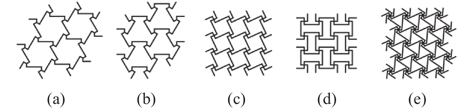
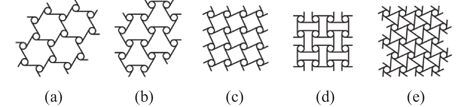
根据结构形式和变形机理的不同, 拉胀超材料大致可归类为纤维增强层压型拉胀复合材料, 拉胀纱, 拉胀泡沫, 拉胀折纸和拉胀蜂窝材料五种形式[6,26,29-32]. 拉胀蜂窝材料具有规则的元胞结构, 非常便于设计、优化和制备, 因此近些年得到了更广泛的关注. 根据微结构的几何形式和主导的变形机理, 拉胀蜂窝材料又可以进一步划分为内凹型拉胀蜂窝材料(具有内凹角, 具有轴对称性质)和手性拉胀蜂窝材料(具有旋转对称性质, 变形时伴随着旋转)[33-34]. 相较于内凹型拉胀材料, 手性拉胀材料在大变形下的拉胀性能表现更好, 并且可容许更大的制造误差[35-38]. 传统手性拉胀材料的元胞结构由中心圆环和与之相切外接组成. 经典的手性拉胀材料包括传统手性拉胀材料和缺失支柱手性拉胀材料两种材料形式. 根据与单个圆环连结的手臂个数及手臂与相邻两圆环的连结形式, 传统手性拉胀材料包括三手臂手性、三手臂反手性、四手臂手性、四手臂反手性及六手臂手性拉胀材料[35,39-41](图1). 缺失支柱手性拉胀材料可视为将传统手性拉胀材料的圆环替换为绑扎桁架而构成[34,42-48](图2). 其余手性拉胀材料均可视为由这两种材料演变而成.
![]() 图 1 传统手性拉胀材料: (a) 三手臂; (b) 反三手臂; (c) 四手臂; (d) 反四手臂; (e) 六手臂Figure 1. (a) Tri-, (b) anti-tri-, (c) tetra-, (d) anti-tetra-, (e) hexa-chiral honeycombs
图 1 传统手性拉胀材料: (a) 三手臂; (b) 反三手臂; (c) 四手臂; (d) 反四手臂; (e) 六手臂Figure 1. (a) Tri-, (b) anti-tri-, (c) tetra-, (d) anti-tetra-, (e) hexa-chiral honeycombs![]() 图 2 缺失支柱手性拉胀材料: (a) 三手臂; (b) 反三手臂; (c) 四手臂; (d) 反四手臂; (e) 六手臂Figure 2. (a) Tri-, (b) anti-tri-, (c) tetra-, (d) anti-tetra-, (e) hexa-missing rib honeycombs
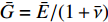
图 2 缺失支柱手性拉胀材料: (a) 三手臂; (b) 反三手臂; (c) 四手臂; (d) 反四手臂; (e) 六手臂Figure 2. (a) Tri-, (b) anti-tri-, (c) tetra-, (d) anti-tetra-, (e) hexa-missing rib honeycombs传统手性拉胀材料的拉胀效应主要源自其中心圆环的转动和手臂的弯曲. 然而, 已有研究表明在大变形时其中心圆环容易发生畸变, 旋转效应相应减弱, 进而导致拉胀性能的迅速劣化[35]. 因此, 传统手性拉胀材料无法在大变形范围内具备恒定的负泊松比, 为其实际的工程应用带来了困难. 根据Simth等[48]、Liu等[43]以及作者团队[3,46-47]的研究表明, 缺失支柱拉胀材料可以在较大的应变范围内表现出恒定的泊松比. 与传统手性拉胀材料类似, 缺失支柱手性拉胀材料的拉胀效应也主要源自其中心绑扎桁架的转动和手臂的弯曲. 但由于组成中心绑扎桁架的梁之间缺乏支撑, 初始的缺失支柱手性拉胀材料的旋转效应较弱, 因而其拉胀性能也较弱. 作者团队[47]在具有初始面内各向同性的六手臂缺失支柱手性拉胀材料的中心绑扎桁架中引入了简单的六边形结构支撑, 发展了增强六手臂(直臂)缺失支柱手性拉胀材料(图3(a)). 该拉胀材料可以在大应变范围内具有可调的恒定负泊松比. 特别是, 通过调整几何参数, 该拉胀材料可在近30%的应变范围内具有趋近于−1的负泊松比. 众所周知, 各向同性结构材料的等效剪切模量为
$\bar G ={{\bar E}}/({{1 + \bar \nu }})$ ($ \bar E $ 和$ \bar \nu $ 分别为等效弹性模量和泊松比). 因此, 结构材料的负泊松比趋于−1时, 其剪切模量理论上趋于无穷大, 具有绝佳的抗剪性能. 从而, 增强六手臂(直臂)缺失支柱手性拉胀材料具有广阔的工程应用前景. 为进一步增大具有恒定负泊松比的应变范围, 作者团队还进一步发展了增强六手臂(曲臂)缺失支柱手性拉胀材料(图3(b)).但作者团队的前期工作仅局限于有限元分析, 缺乏对所发展的拉胀材料力学参数的理论描述, 无法根据目标性能进行有效的结构参数设计, 限制了其工程应用. 而参数化设计有助于对超材料进行结构优化, 从而促进其工程应用[49-50]. 本文所研究的拉胀蜂窝材料大都由细长结构组成, 可被假设为欧拉−伯努利梁[51]. 大量研究证实利用能量法(如卡氏定理)可有效地推导拉胀蜂窝材料力学参数的理论表达式. 因此, 本文致力于利用能量法给出前期发展的增强六手臂缺失支柱手性拉胀材料等效弹性模量和泊松比的理论表达式, 以期为拉胀材料的有效参数设计提供理论指导.
1. 几何模型
增强六手臂缺失支柱手性拉胀材料为典型二维结构材料. 其元胞如图3所示, 由“Z”形梁结构及增强六边形组成. 元胞还可视为由六个最小代表单元(红色虚线部分)阵列而成. 直臂结构的元胞几何形状可由五个独立参数确定, 即“Z”形梁长手臂长度L; Z”形梁短手臂长度r; “Z”形梁内角
$ \varphi $ ; 增强六边形结构边长l以及所有梁结构的宽度t (如图3(a)所示). 由图3可见, 元胞结构的绑扎桁架由“Z”形梁短手臂及增强六边形组成, 而“Z”形梁长手臂则与其相接. 因此, 为后续叙述方便, 下文中“Z”形梁长手臂和短手臂分别记为外手臂和内手臂.将图3(a)中的直手臂替换为等长圆弧即可得相应曲臂拉胀材料. 因此, 要描述曲臂材料的元胞几何形状, 还需引入表征其半径的参数R. 需要指出的是前述所有表征梁长度和半径的参数均沿梁中性轴测量.
为后续描述方便, 本文定义了参数b来表征增强六边形与手臂之间的距离. b可由r和l表示, 即
$$ b = r - l $$ (1) 另外, 本文还引入了增强率p及手臂比 q分别来描述材料增强的程度及内外手臂长度的比例. p和q的表达式为
$$ p = 1 - \frac{b}{r} $$ (2a) $$ q = \frac{L}{{2r}} $$ (2b) 2. 等效力学参数理论表达式(小变形)
如前所述, 本文所研究的两种拉胀材料均可视为由多个欧拉−伯努利梁组成. 因而, 可利用能量法推导其等效弹性模量和泊松比. 利用能量法推导等效力学参数通常的做法是: 首先, 对阵列的拉胀材料施加远场应力; 然后, 取最小代表性单元, 并根据几何和受力条件确定各梁的受力状态; 最后, 推导最小代表性单元的应变能, 并根据卡氏定理和几何相容条件获得等效弹性模量和泊松比的表达式.
对于具有简单最小代表单元构型的拉胀材料(如最小代表单元具有三角形边界的三手臂传统/缺失支柱反手性拉胀材料, 最小代表单元具有矩形边界的四手臂传统/缺失支柱反手性拉胀材料等), 最小代表单元的受力状态可由几何和远场应力条件确定[3,37,46]. 然而, 对于本文所研究的拉胀材料, 其最小代表单元的边界较为复杂(图3(a)), 无法通过传统方法推导其力学参数的理论表达式. Liu等[43]发展了基于最小代表单元整体受力平衡条件和变形协调条件的方法, 准确地推导了具有弱连结的六手臂缺失支柱手性拉胀材料的力学参数的理论表达式. 六手臂缺失支柱手性拉胀材料与Liu等[43]所提出的材料具有相似的构型, 因此, 本文将基于同样的思路来进行理论推导.
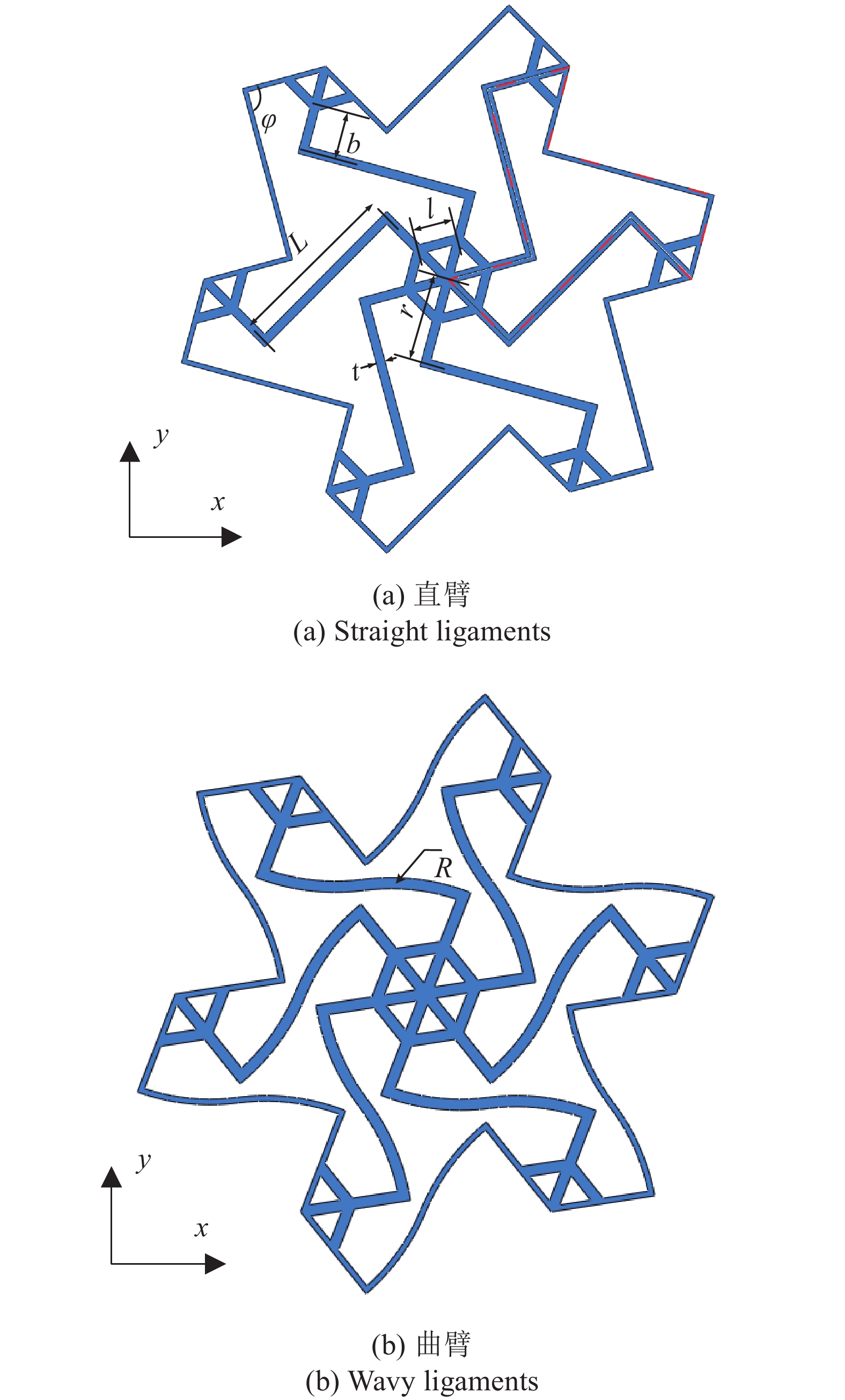
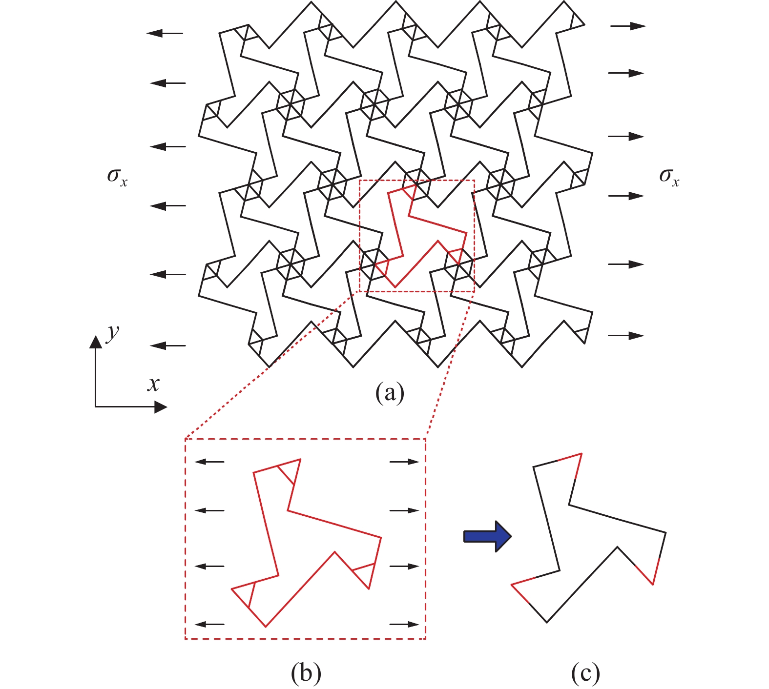
以增强六手臂(直臂)缺失支柱手性拉胀材料为例. 对其施加如图4(a)所示远场拉应力, 其最小代表单元的受力情况如图4(b)所示. 该最小代表单元由三个增强杆和三根“Z”型梁组成. 前期研究表明[3], 由增强杆和“Z”型梁组成三角形单元体在结构整体变形时几乎不会发生畸变, 局部应变非常小, 可以视为刚体. 因此, 推导最小代表单元的计算应变能时, 可忽略三角形元素的贡献. 最小代表单元可进一步简化为只由三根 “Z”型梁相互连结而成(图4(c)), 并且标注为红色的部分(对应于三角形单元体)假定为刚体, 不对应变能做贡献. 另外, 如图4(c)所示的等效最小代表单元的各梁段为连续梁, 刚体和变形体连接处满足挠度和转角连续性条件.
![]() 图 4 (a) 阵列结构受远程应力示意图; (b) 最小代表单元受力图;(c) 等效最小代表单元Figure 4. (a) Schematic diagram of an enhanced hexa-missing rib lattice under far field uniaxial loading. (b) The related free boundary diagram of the smallest repeated unit. (c) The effective smallest repeated unit
图 4 (a) 阵列结构受远程应力示意图; (b) 最小代表单元受力图;(c) 等效最小代表单元Figure 4. (a) Schematic diagram of an enhanced hexa-missing rib lattice under far field uniaxial loading. (b) The related free boundary diagram of the smallest repeated unit. (c) The effective smallest repeated unit2.1 任意形状的欧拉−伯努利梁力学模型
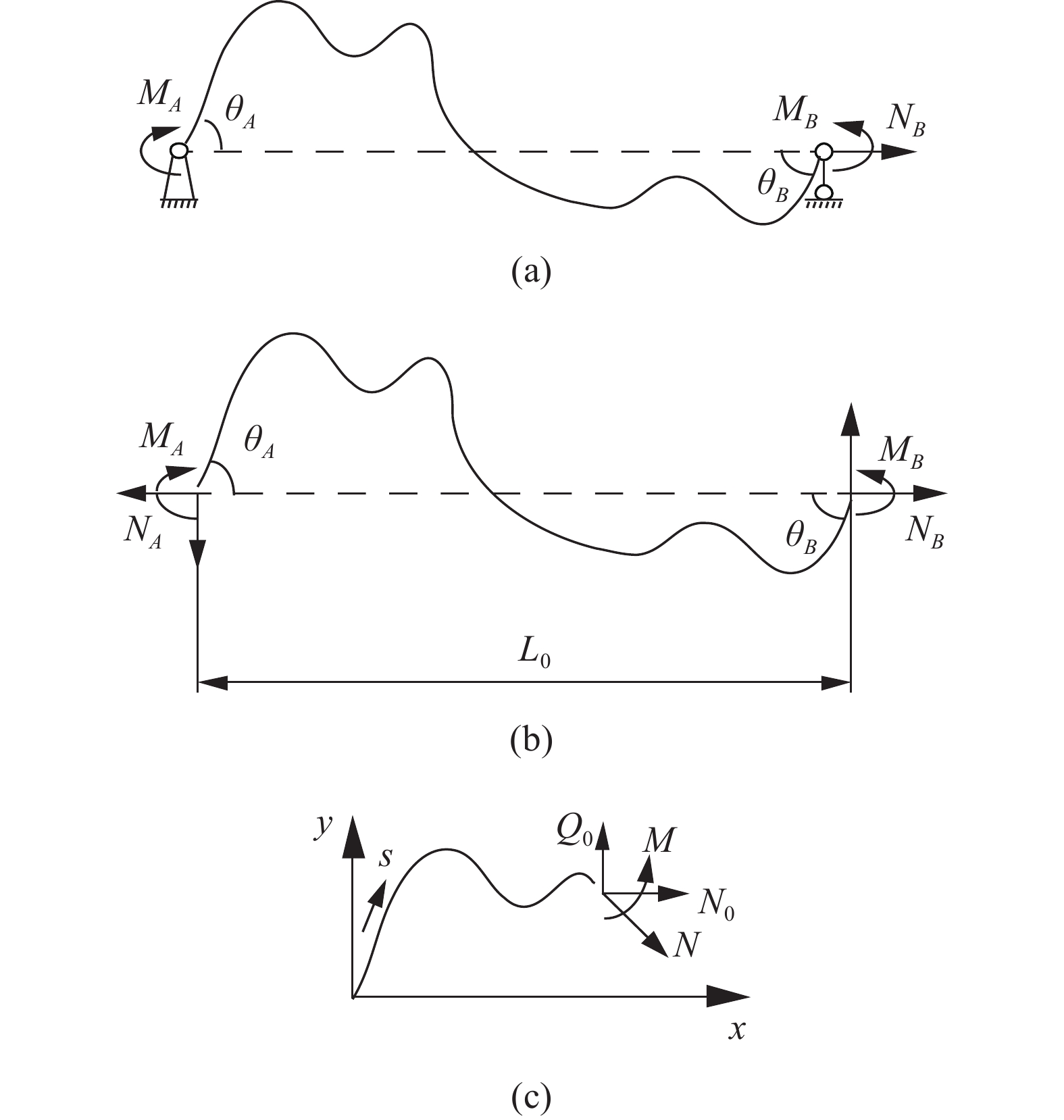
要确定最小代表单元的整体受力和变形条件, 首要分析其“Z”形梁组件的力−位移关系. 图4(c)所示的“Z”形梁变形时, 可简化为一端固定铰接并作用有集中力偶
$ {M_A} $ , 另一端滑动铰接, 并作用有集中力偶$ {M_B} $ 和水平集中力$ {N_0} $ 的简支梁(如图5(a)所示). 去掉支座, 代之以力, 其对应的受力情况如图5(b)所示. 由图5(b)易知![]() 图 5 任意欧拉−伯努利梁结构受力图Figure 5. Force diagram of an Euler–Bernoulli beam with arbitrary shape
图 5 任意欧拉−伯努利梁结构受力图Figure 5. Force diagram of an Euler–Bernoulli beam with arbitrary shape$$ {Q_0} = {{\left( {{M_A} - {M_B}} \right)} \mathord{\left/ {\vphantom {{\left( {{M_A} - {M_B}} \right)} {{L_0}}}} \right. } {{L_0}}} $$ (2) 为了更具有普适性, “Z”形梁上任一截面(以轴线长度s标记, 如图5(c)所示)的坐标可构造为轴线长度s的函数, 即
$$ x = x{\text{ }}(s){\text{, }}\qquad y = y{\text{ }}(s){\text{ }} $$ (3) 则截面s上的轴力N和弯矩M与x和y方向上的内力
$ {N_0} $ 和$ {Q_0} $ 有关, 分别为$$\tag{4a} N(s) = {N_0} x'(s) + {Q_0} y'(s)\quad $$ $$\tag{4b} M(s) = {M_A} + {N_0} y(s) - {Q_0} x(s) $$ 其中,
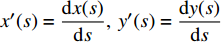
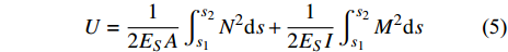
$x'(s) = \dfrac{{{\rm{d}}x(s)}}{{{\rm{d}}s}},{\text{ }}y'(s) = \dfrac{{{\rm{d}}y(s)}}{{{\rm{d}}s}}$ . 忽略剪切变形的贡献, 梁组件应变能可表示为$$ U = \frac{1}{{2{E_S}A}}\int_{{s_1}}^{{s_2}} {{N^2}{\rm{d}}s} + \frac{1}{{2{E_S}I}}\int_{{s_1}}^{{s_2}} {{M^2}{\rm{d}}s} $$ (5) 其中,
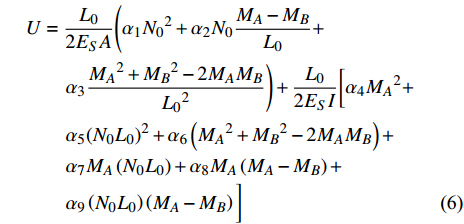
$ {E_S} $ 为基体材料的弹性模量;$ {E_S}A = {E_S}t $ 和${E_S}I{{ = }} {E_S}{t^3}/12$ 分别为单位厚度梁的拉伸刚度和弯曲刚度.联合式(2)~式(5), 可得
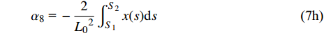
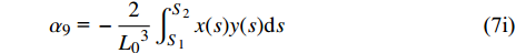
$$ \begin{split} & U = \frac{{{L_0}}}{{2{E_S}A}}\Bigg( {\alpha _1}{N_0}^2 + {\alpha _2}{N_0}\frac{{{M_A} - {M_B}}}{{{L_0}}} + \\&\qquad {\alpha _3}\frac{{{M_A}^2 + {M_B}^2 - 2{M_A}{M_B}}}{{{L_0}^2}} \Bigg)+ \frac{{{L_0}}}{{2{E_S}I}}\bigg[ {\alpha _4}{M_A}^2 +\\&\qquad {\alpha _5}{\left( {{N_0}{L_0}} \right)^2} + {\alpha _6}\left( {{M_A}^2 + {M_B}^2 - 2{M_A}{M_B}} \right) + \\&\qquad {\alpha _7}{M_A}\left( {{N_0}{L_0}} \right) + {\alpha _8}{M_A}\left( {{M_A} - {M_B}} \right) + \\&\qquad {\alpha _9}\left( {{N_0}{L_0}} \right)\left( {{M_A} - {M_B}} \right) \bigg] \end{split} $$ (6) 式中,
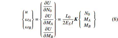
$ {\alpha _i}{\text{ }}(i = 1,{\text{ }}2,{\text{ }}\cdots,{\text{ }}9) $ 为一组只取决于结构形状的无量纲参数, 表达式为$$\tag{7a} {\alpha _1}{\text{ = }}\frac{1}{{{L_0}}}\int_{{S_1}}^{{S_2}} {{{\left( {x'(s)} \right)}^2}{\rm{d}}s} $$ $$\tag{7b} {\alpha _2}{\text{ = }}\frac{2}{{{L_0}}}\int_{{S_1}}^{{S_2}} {x'(s)y'(s)} {\rm{d}}s $$ $$\tag{7c} {\alpha _3}{\text{ = }}\frac{1}{{{L_0}}}\int_{{S_1}}^{{S_2}} {{{\left( {y'(s)} \right)}^2}{\rm{d}}s} $$ $$\tag{7d} {\alpha _4}{\text{ = }}\frac{1}{{{L_0}}}\int_{{S_1}}^{{S_2}}1 {\rm{d}}s $$ $$\tag{7e} {\alpha _5}{\text{ = }}\frac{1}{{{L_0}^3}}\int_{{S_1}}^{{S_2}} {{{\left( {y'(s)} \right)}^2}} {\rm{d}}s $$ $$\tag{7f} {\alpha _6}{\text{ = }}\frac{1}{{{L_0}^3}}\int_{{S_1}}^{{S_2}} {{{\left( {x'(s)} \right)}^2}} {\rm{d}}s $$ $$\tag{7g} {\alpha _7}{\text{ = }}\frac{2}{{{L_0}^2}}\int_{{S_1}}^{{S_2}} {y(s)} {\rm{d}}s $$ $$\tag{7h} {\alpha _8}{\text{ = }} - \frac{2}{{{L_0}^2}}\int_{{S_1}}^{{S_2}} {x(s)} {\rm{d}}s $$ $$\tag{7i} {\alpha _9}{\text{ = }} - \frac{2}{{{L_0}^3}}\int_{{S_1}}^{{S_2}} {x(s)} y(s){\rm{d}}s $$ 运用卡氏定理, 可以得出梁滑动端的位移(记为u, 沿x方向)及两端旋转角
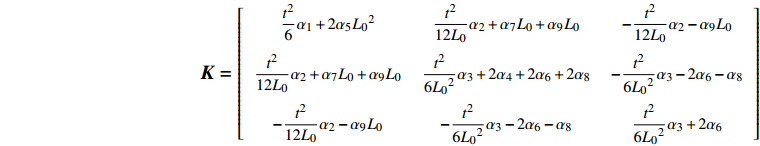
$ {\omega _A} $ 和$ {\omega _B} $ 的表达式为$$ \left\{ \begin{gathered} u \\ {\omega _A} \\ {\omega _B} \\ \end{gathered} \right\} = \left\{ \begin{gathered} \frac{{\partial U}}{{\partial {N_0}}} \\ \frac{{\partial U}}{{\partial {M_A}}} \\ \frac{{\partial U}}{{\partial {M_B}}} \\ \end{gathered} \right\} = \frac{{{L_0}}}{{2{E_S}I}}{\boldsymbol{K}}\left\{ {\begin{array}{*{20}{c}} {{N_0}} \\ {{M_A}} \\ {{M_B}} \end{array}} \right\} $$ (8) 式中,
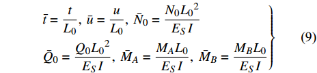
$\dfrac{{{L_0}}}{{2{E_S}I}}{\boldsymbol{K}}$ 为柔度系数,${\boldsymbol{K}}$ 的表达式见附录A.为简化计算, 使用归一化宽度(
$ \bar t $ )和位移($ \bar u $ )和力($ {\bar N_0} $ 和$ {\bar Q_0} $ )和力矩($ {\bar M_A} $ 和$ {\bar M_B} $ )来替换实际宽度(t)和位移(u)和力($ {N_0} $ 和$ {Q_0} $ )和力矩($ {M_A} $ 和$ {M_B} $ ), 即$$ \left.\begin{split} & \bar t = \frac{t}{{{L_{\text{0}}}}},{\text{ }}\bar u = \frac{u}{{{L_{\text{0}}}}},{\text{ }}{{\bar N}_0} = \frac{{{N_0}{L_0}^2}}{{{E_S}I}} \\& {{\bar Q}_0} = \frac{{{Q_0}{L_0}^2}}{{{E_S}I}},{\text{ }}{{\bar M}_A} = \frac{{{M_A}{L_0}}}{{{E_S}I}},{\text{ }}{{\bar M}_B} = \frac{{{M_B}{L_0}}}{{{E_S}I}} \end{split} \right\}$$ (9) 对式(8)取逆, 并代入式(9)所示的归一化关系, 可得
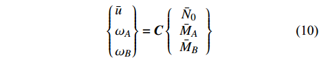
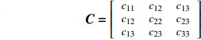
$$ \left\{ \begin{gathered} {\bar u} \\ {\omega _A} \\ {\omega _B} \\ \end{gathered} \right\} = {\boldsymbol{C}}\left\{ {\begin{array}{*{20}{c}} {{{\bar N}_0}} \\ {{{\bar M}_A}} \\ {{{\bar M}_B}} \end{array}} \right\} $$ (10) 其中,
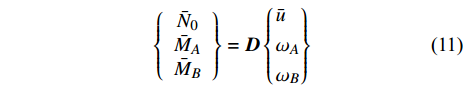
${\boldsymbol{C}}$ 为柔度矩阵, 表达式见附录A. 其逆形式为$$ \left\{ {\begin{array}{*{20}{c}} {{{\bar N}_0}} \\ {{{\bar M}_A}} \\ {{{\bar M}_B}} \end{array}} \right\} = {\boldsymbol{D}}\left\{ \begin{gathered} {\bar u} \\ {\omega _A} \\ {\omega _B} \\ \end{gathered} \right\} $$ (11) 其中,
${\boldsymbol{D}} = {{\boldsymbol{C}}^{ - 1}}$ 为刚度矩阵.2.2 增强六手臂缺失支柱拉胀材料力学模型
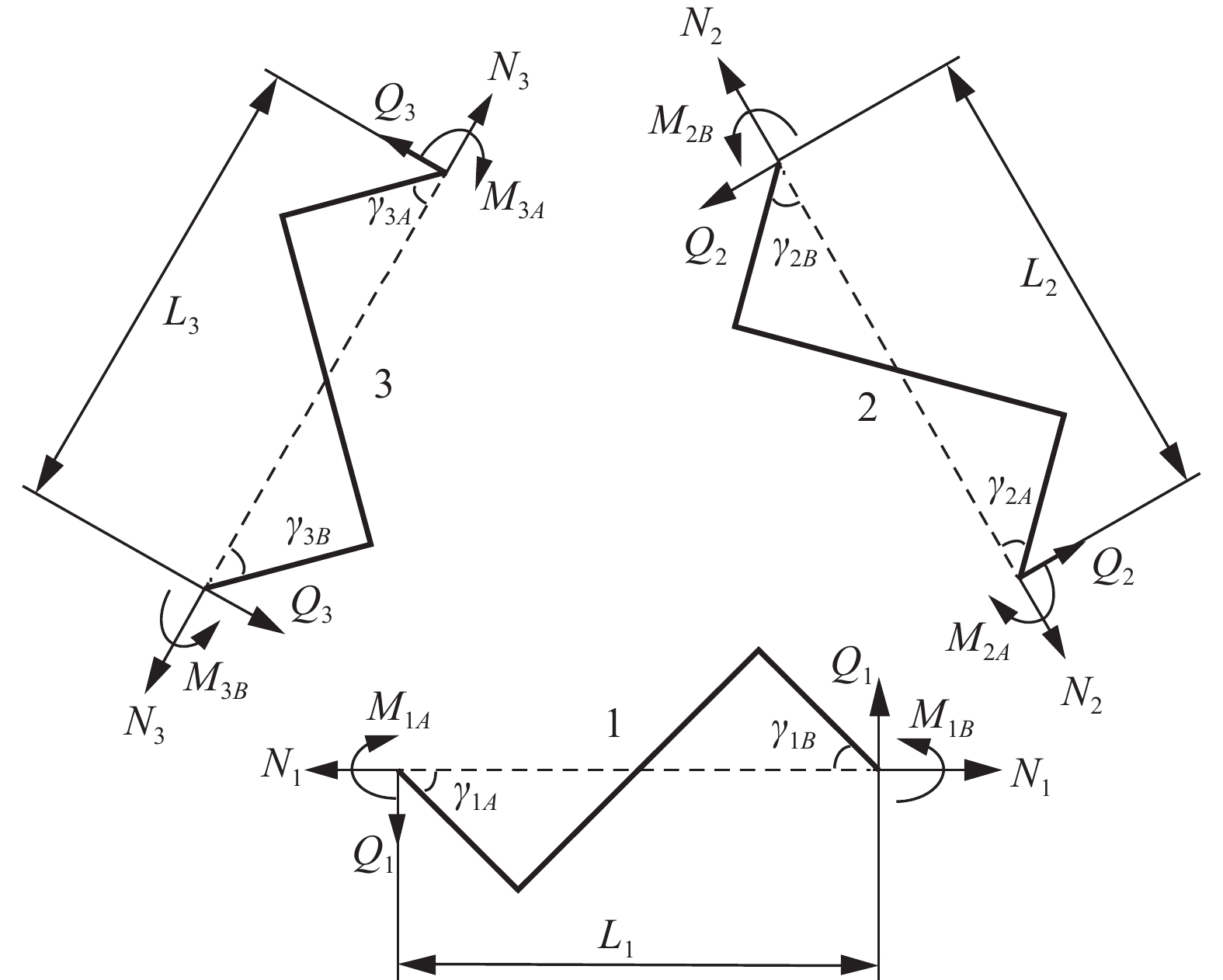
如前所述, 增强六手臂缺失支柱拉胀材料的最小代表单元可简化为如图4(c)所示的结构. 打开三根“Z”形梁之间的连结, 受力情况如图6所示.
![]() 图 6 最小代表单元各“Z”型梁受力图Figure 6. Force diagram of the zigzag ligaments of the smallest repeated unit
图 6 最小代表单元各“Z”型梁受力图Figure 6. Force diagram of the zigzag ligaments of the smallest repeated unit为描述方便, 按照逆时针将“Z”形梁分别命名为1, 2, 3, 并令
$ {N_i} $ ,$ {M_i} $ ,$ {Q_i} $ (i = 1, 2, 3)表示结构的轴力、弯矩和剪力.联立式(2)和式(9)可得
$$ {\bar M_{iA}} - {\bar M_{iB}} = {\bar Q_i} $$ (12) 进一步根据梁2, 3连结处及梁1, 2连结处的受力平衡, 可得
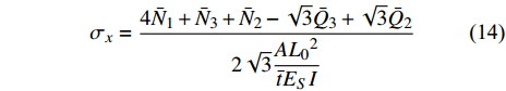
$$\tag{13a} \sqrt 3 {\bar N_3} + \sqrt 3 {\bar N_2} + {\bar Q_3} - {\bar Q_2} = 0 $$ $$\tag{13b} 2{\bar Q_1} + {\bar Q_2} - \sqrt 3 {\bar N_2} = 0 $$ 再考虑图4(b)所示的受力情况, 根据水平方向受力平衡, 可得
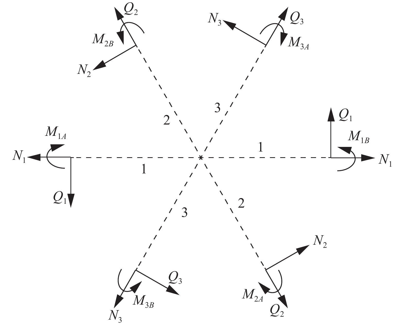
$$ {\sigma _x} = \frac{{4{{\bar N}_1} + {{\bar N}_3} + {{\bar N}_2} - \sqrt 3 {{\bar Q}_3} + \sqrt 3 {{\bar Q}_2}}}{{2\sqrt 3 \dfrac{{A{L_0}^2}}{{\bar t{E_S}I}}}} $$ (14) 如前所述, 每个元胞包含六个最小代表单元(图3(a)). 取元胞中心点附近的微小分离体, 其受力情况如图7所示. 根据力矩平衡条件, 可得
![]() 图 7 元胞中心节点区受力图Figure 7. Force diagram of an area surrounding the central point of the unit-cell
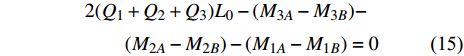
图 7 元胞中心节点区受力图Figure 7. Force diagram of an area surrounding the central point of the unit-cell$$ \begin{split} & 2({Q_1} + {Q_2} + {Q_3}){L_0} - ({M_{3A}} - {M_{3B}})- \\&\qquad ({M_{2A}} - {M_{2B}}) - ({M_{1A}} - {M_{1B}}) = 0 \end{split} $$ (15) 将式(12)代入式(15), 进一步可得
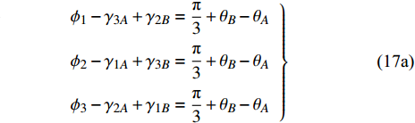
$$ ({\bar M_{1A}} - {\bar M_{1B}}) + ({\bar M_{2A}} - {\bar M_{2B}}) + ({\bar M_{3A}} - {\bar M_{3B}}) = 0 $$ (16) 本文仅考虑线弹性小变形情况, 则最小代表单元三个“Z”形梁组件的三个连结点形成的图形在变形前后适中保持为封闭的三角形(如图8所示). 根据几何条件和变形相容条件, 可得
![]() 图 8 最小代表单元变形示意图Figure 8. Schematic diagram of the deformation of smallest repeated unit
图 8 最小代表单元变形示意图Figure 8. Schematic diagram of the deformation of smallest repeated unit$$\tag{17a} \left. {\begin{array}{l} {{\phi _1} - {\gamma _{3A}} + {\gamma _{2B}} = \dfrac{{\text{π}} }{3} + {\theta _B} - {\theta _A}} \\ {{\phi _2} - {\gamma _{1A}} + {\gamma _{3B}} = \dfrac{{\text{π}} }{3} + {\theta _B} - {\theta _A}} \\ {{\phi _3} - {\gamma _{2A}} + {\gamma _{1B}} = \dfrac{{\text{π}} }{3} + {\theta _B} - {\theta _A}} \end{array}} \right\} $$ $$ \tag{17b} \frac{{{L_1}}}{{\sin {\phi _1}}} = \frac{{{L_2}}}{{\sin {\phi _2}}} = \frac{{{L_3}}}{{\sin {\phi _3}}} $$ $$ \tag{17c} {\phi _1} + {\phi _2} + {\phi _3}{\text{ = }}{\text{π}} $$ 其中,
$ {\theta _A} $ ,$ {\theta _B}{\text{ }} $ 为杆件变形前两端切线与x轴的夹角(见图5);$ {\gamma _{iA}} $ ,$ {\gamma _{iB}} $ 为变形后夹角;$ {\phi _1}{\text{ }} $ ,$ {\phi _2}{\text{ }} $ 和$ {\phi _3} $ 为三角形变形后内角,$ {L_1} $ ,$ {L_2} $ 和$ {L_3} $ 为变形后梁1, 2和3端点之间的直线长度.由式(17b)进一步可得
$$ {L_1}\sin {\phi _3} = {L_3}\sin {\phi _1} $$ (18) 两边取微分, 有
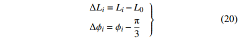
$$ \Delta {L_3}\sin {\phi _1} - \Delta {L_1}\sin {\phi _3}{\text{ = }}\Delta {\phi _3}{L_1}\cos {\phi _3} - \Delta {\phi _1}{L_3}\cos {\phi _1} $$ (19) 其中
$$\left.\begin{array}{l} \Delta {L_i} = {L_i} - {L_0}\\ \Delta {\phi _i} = {\phi _i} - \dfrac{{\text{π}} }{3} \end{array}\right\}$$ (20) 小变形时可认为
$$\left.\begin{array}{l} {\phi _1} \approx {\phi _3} \approx {{\text{π}} / 3}\\ {L_1} \approx {L_3} \approx {L_0} \end{array}\right\}$$ (21) 则式(17)可改写为
$$ \sqrt{3}(\Delta {L}_{3}-\Delta {L}_{1})/{L}_{0}=\Delta {\phi }_{3}-\Delta {\phi }_{1} $$ (22) 联立式(17a)、式(20)和式(21)可得
$$ {\bar u_3} - {\bar u_1} = \frac{1}{{\sqrt 3 }}({\omega _{3A}} + {\omega _{2B}} - {\omega _{2A}} - {\omega _{1B}}) $$ (23) 式中
$$ {u_i} = \frac{{\Delta {L_i}}}{{{L_0}}},{\text{ }}{\omega _{iA}} = {\theta _A} - {\gamma _{iA}},{\text{ }}{\omega _{iB}} = {\gamma _{iB}} - {\theta _B} $$ (24) 同理可得
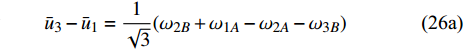
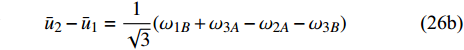
$$ {\bar u_2} - {\bar u_1} = \frac{1}{{\sqrt 3 }}({\omega _{3A}} + {\omega _{2B}} - {\omega _{1A}} - {\omega _{3B}}) $$ (25) 考虑最小代表单元的镜像结构(如图8(b)所示), 易知
$$\tag{26a} {\bar u_3} - {\bar u_1} = \frac{1}{{\sqrt 3 }}({\omega _{2B}} + {\omega _{1A}} - {\omega _{2A}} - {\omega _{3B}}) $$ $$\tag{26b} {\bar u_2} - {\bar u_1} = \frac{1}{{\sqrt 3 }}({\omega _{1B}} + {\omega _{3A}} - {\omega _{2A}} - {\omega _{3B}}) $$ 联立式(17a)和式(24)可知
$$ {\omega _{1A}} + {\omega _{2A}} + {\omega _{3A}} + {\omega _{1B}} + {\omega _{2B}} + {\omega _{3B}} = 0 $$ (27) 图8(a)所示的最小代表单元在水平方向和竖直方向变形前后的长度分别为
$$\tag{28a} {L_{x0}} = {L_0} $$ $$\tag{28b} {L_{y0}} = {L_0}\sin \left( {{{\text{π}} \mathord{\left/ {\vphantom {\pi 3}} \right. } 3}} \right) $$ $$\tag{28c} {L}_{y}=({L}_{3}\mathrm{sin}{\phi }_{2} + {L}_{2}\mathrm{sin}{\phi }_{3})/2 $$ $$\tag{28d} {L_x} = {L_3}\cos {\phi _2} + {L_2}\cos {\phi _3} $$ 变形后的协调条件为, 梁“2”和“3”在水平方向的投影长度之和与梁“1”的长度相等, 即
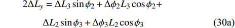
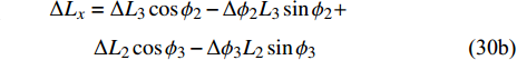
$$ {L_3}\cos {\phi _2} + {L_2}\cos {\phi _3}{\text{ = }}{L_1} $$ (29) 对式(28c)、式(28d)和式(29)微分可得
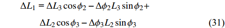
$$ \begin{split} & 2\Delta {L_y} = \Delta {L_3}\sin {\phi _2} + \Delta {\phi _2}{L_3}\cos {\phi _2}+ \\ &\qquad \Delta {L_2}\sin {\phi _3} + \Delta {\phi _3}{L_2}\cos {\phi _3} \end{split} \tag{30a}$$ $$ \begin{split}& \Delta {L_x} = \Delta {L_3}\cos {\phi _2} - \Delta {\phi _2}{L_3}\sin {\phi _2} +\\ &\qquad \Delta {L_2}\cos {\phi _3} - \Delta {\phi _3}{L_2}\sin {\phi _3} \end{split} \tag{30b}$$ $$ \begin{split} & \Delta {L_1}{\text{ = }}\Delta {L_3}\cos {\phi _2} - \Delta {\phi _2}{L_3}\sin {\phi _2}+ \qquad\qquad\\ &\qquad \Delta {L_2}\cos {\phi _3} - \Delta {\phi _3}{L_2}\sin {\phi _3} \end{split} $$ (31) 由式(30b)和式(31)可知
$$ \Delta {L_x} = \Delta {L_1} $$ (32) 则最小代表单元的水平平均应变为
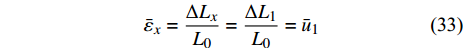
$$ {\bar \varepsilon _x} = \frac{{\Delta {L_x}}}{{{L_0}}} = \frac{{\Delta {L_1}}}{{{L_0}}} = {\bar u_1} $$ (33) 联立式(21)、式(24)和式(30a)可得
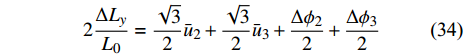
$$ 2\frac{{\Delta {L_y}}}{{{L_0}}} = \frac{{\sqrt 3 }}{2}{\bar u_2} + \frac{{\sqrt 3 }}{2}{\bar u_3} + \frac{{\Delta {\phi _2}}}{2} + \frac{{\Delta {\phi _3}}}{2} $$ (34) 联立式(17a)、式(20)及式(27)可知
$$ \Delta {\phi _2} + \Delta {\phi _3} = {\omega _{3A}} + {\omega _{2B}} $$ (35) 进一步联立式(26)、式(27)、式(34)和式(35)可知
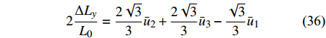
$$ 2\frac{{\Delta {L_y}}}{{{L_0}}} = \frac{{2\sqrt 3 }}{3}{\bar u_2} + \frac{{2\sqrt 3 }}{3}{\bar u_3} - \frac{{\sqrt 3 }}{3}{\bar u_1} $$ (36) 则最小代表单元的竖直平均应变可进一步表示为
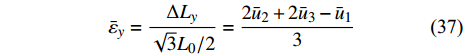
$$ {\bar \varepsilon _y} = \frac{{\Delta {L_y}}}{{\sqrt 3 {L_0}/2}} = \frac{{2{{\bar u}_2} + 2{{\bar u}_3} - {{\bar u}_1}}}{3} $$ (37) 材料的等效弹性模量(以基体材料弹性模量进行归一化)和泊松比分别为
$$ \overline Y {\text{ = }}\frac{{{\sigma _x}}}{{{{\bar \varepsilon }_x}{E_S}}} $$ (38) $$ \bar \nu {\text{ = }} - \frac{{{\varepsilon _y}}}{{{\varepsilon _x}}} $$ (39) 借助Maple软件, 联立方程式(11)~式(14)、式(17)、式(23)、式(25)~式(27)、式(33)及式(37)~式(39)可得等效弹性模量和泊松比分别为
$$ \bar Y{\text{ = }}\frac{{\sqrt 3 ({d_{11}} + {d_{22}} - 2{d_{23}} + {d_{33}})\left[ { - {{({d_{12}} - {d_{13}})}^2} + {d_{11}}({d_{22}} - 2{d_{23}} + {d_{33}})} \right]}}{{6{L_0}^3\left[ { - 2{{({d_{12}} - {d_{13}})}^2} + ({d_{22}} - 2{d_{23}} + {d_{33}})(3{d_{11}} + {d_{22}} - 2{d_{23}} + {d_{33}})} \right]}} $$ (40) $$ \bar \nu {\text{ = }}\frac{{2{{({d_{12}} - {d_{13}})}^2} - ({d_{11}} - {d_{22}} + 2{d_{23}} - {d_{33}})({d_{22}} - 2{d_{23}} + {d_{33}})}}{{2{{({d_{12}} - {d_{13}})}^2} - ({d_{22}} - 2{d_{23}} + {d_{33}})(3{d_{11}} + {d_{22}} - 2{d_{23}} + {d_{33}})}} $$ (41) 针对特定的结构形式, 给出“Z”形梁的曲线描述方程, 进一步给出式(7)中无量纲参数的具体形式, 并带入式(40)和式(41)进行化简, 即可得材料最终的等效弹性模量和泊松比的理论表达式.
需要指出的是, 本节所描述的六手臂缺失支柱型手性拉胀材料等效力学参数的理论推导过程与Liu等[43]的思路一致. 但他们的工作中对如何利用平衡条件得到方程式(12)~式(14), 及利用变形协调条件得到方程式(33)和式(37)阐述并不清晰. 本文详细地陈述了这两个推导过程, 增加了文章的可读性.
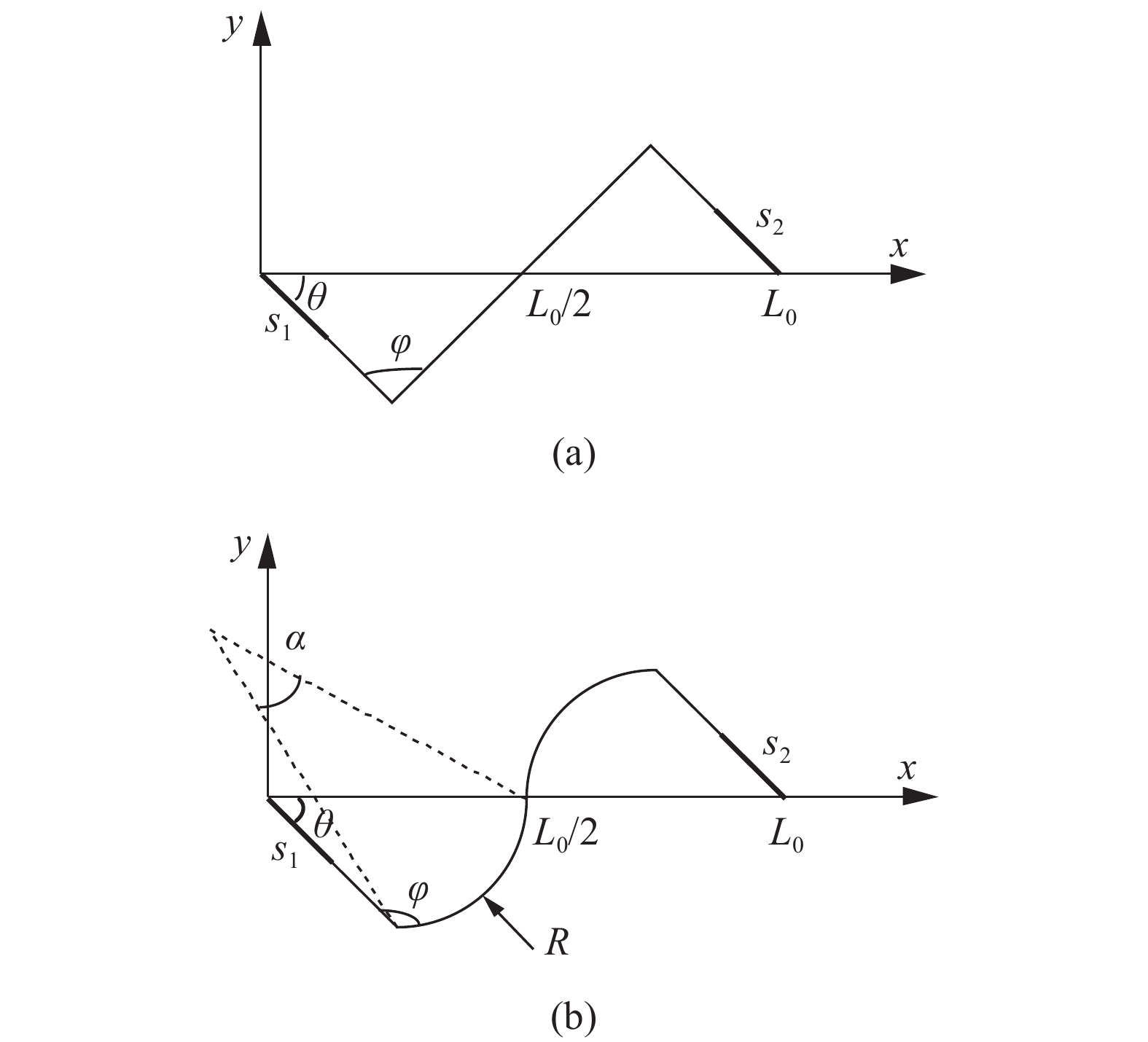
增强六手臂缺失支柱手性拉胀材料和增强六手臂(曲臂)缺失支柱手性拉胀材料的代表性“Z”形梁的计算模型如图9所示. 两种材料的曲线描述方程可见附录A.
![]() 图 9 (a) 直臂与 (b) 曲臂结构计算模型Figure 9. Calculation diagram of the enhanced hexa-missing rib auxetic honeycombs with (a) straight ligament and (b) wavy ligament
图 9 (a) 直臂与 (b) 曲臂结构计算模型Figure 9. Calculation diagram of the enhanced hexa-missing rib auxetic honeycombs with (a) straight ligament and (b) wavy ligament需要指出的是, 通常情况下两种结构弹性模量和泊松比的理论表达式为包含上千项的多项式, 无法继续化简. 但根据理论推导, 作者已经基于MATLAB软件创建了图形用户界面(GUI), 界面如图10所示. 对于直臂结构, 只需输入内手臂长度r, 外手臂长度L, 增强率p, 内角ϕ, 手臂宽度t五个独立参数即可获得特定微结构形式的等效弹性模量和泊松比. 对于曲臂结构, 还需输入外手臂的半径R.
另外, 研究还发现, 在
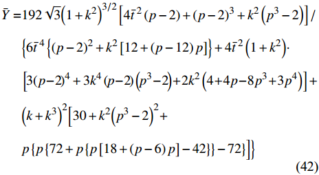
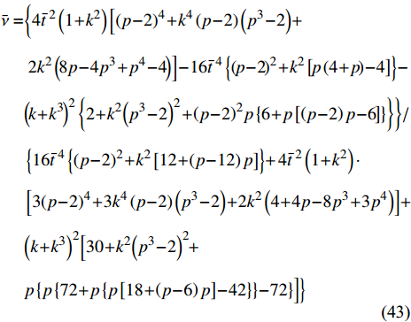
$ L = 2 r $ 这种特定的情况下, 直臂结构的等效弹性模量和泊松比具有简洁的理论表达式, 即![]() 图 10 图形用户界面: (a) 直臂结构计算和(b) 曲臂结构计算Figure 10. Graphical user interface: (a) calculation of auxetics with straight ligaments and (b) calculation of auxetics with wavy ligaments
图 10 图形用户界面: (a) 直臂结构计算和(b) 曲臂结构计算Figure 10. Graphical user interface: (a) calculation of auxetics with straight ligaments and (b) calculation of auxetics with wavy ligaments$$\begin{split} \bar Y =& 192\sqrt 3 {\left( {1 + {k^2}} \right)^{3/2}}\left[ {4{{\bar t}^{\;2}}\left( {p - 2} \right) + {{\left( {p - 2} \right)}^3} + {k^2}\left( {{p^3} - 2} \right)} \right]/\\ & \Big\{ {6{{\bar t}^{\;4}}\left\{ {{{\left( {p - 2} \right)}^2} + {k^2}\left[ {12 + \left( {p - 12} \right)p} \right]} \right\} + 4{{\bar t}^{\;2}}\left( {1 + {k^2}} \right)} \cdot\\ & \left[ {3{{\left( {p - 2} \right)}^4} + 3{k^4}\left( {p - 2} \right)\left( {{p^3} - 2} \right) + 2{k^2}\left( {4 + 4p - 8{p^3} + 3{p^4}} \right)} \right] + \\ & {\left( {k + {k^3}} \right)^2}\Big[ {30 + {k^2}{{\left( {{p^3} - 2} \right)}^2} + } \\ & { {p\left\{ {p\left\{ {72 + p\left\{ {p\left[ {18 + \left( {p - 6} \right)p} \right] - 42} \right\}} \right\} - 72} \right\}} \Big]}\Big\} \end{split} $$ (42) $$\begin{split} \bar \nu = & \biggl\{ {4{{\bar t}^{\;2}}\left( {1 + {k^2}} \right)\left[ {{{\left( {p - 2} \right)}^4} + {k^4}\left( {p - 2} \right)\left( {{p^3} - 2} \right) + } \right.} \\ & \left. {2{k^2}\left( {8p - 4{p^3} + {p^4} - 4} \right)} \right] - 16{{\bar t}^{\;4}}\left\{ {{{\left( {p - 2} \right)}^2} + {k^2}\left[ {p\left( {4 + p} \right) - 4} \right]} \right\} - \\ & {{{\left( {k + {k^3}} \right)}^2}\left\{ {2 + {k^2}{{\left( {{p^3} - 2} \right)}^2} + {{\left( {p - 2} \right)}^2}p\left\{ {6 + p\left[ {\left( {p - 2} \right)p - 6} \right]} \right\}} \right\}} \biggl\}/\\ & \left\{ {16{{\bar t}^{\;4}}\left\{ {{{\left( {p - 2} \right)}^2} + {k^2}\left[ {12 + \left( {p - 12} \right)p} \right]} \right\} + } \right.4{{\bar t}^{\;2}}\left( {1 + {k^2}} \right)\cdot\\ & \left[ {3{{\left( {p - 2} \right)}^4} + 3{k^4}\left( {p - 2} \right)\left( {{p^3} - 2} \right) + 2{k^2}\left( {4 + 4p - 8{p^3} + 3{p^4}} \right)} \right] + \\ & {\left( {k + {k^3}} \right)^2}\Big[ {30 + {k^2}{{\left( {{p^3} - 2} \right)}^2} + } \\ & { {p\left\{ {p\left\{ {72 + p\left\{ {p\left[ {18 + \left( {p - 6} \right)p} \right] - 42} \right\}} \right\} - 72} \right\}} \Big]} \Big\} \end{split} $$ (43) 其中
$ k = \tan \theta $ .3. 等效力学参数理论解讨论及有限元结果对比
本节将系统讨论直臂结构的等效弹性模量和泊松比与几何参数之间的关系, 并将相应结果与有限元模拟进行对比.
为简化分析, 本节所讨论的拉胀材料的手臂长度和手臂宽度之间的比例关系均固定为L: t = 20. 另外, 作者的前期研究表明: 几何参数相同时, 曲臂缺失支柱拉胀材料的负泊松比响应与直臂材料接近(图10也可以证明), 仅在增加保持恒定负泊松比的应变范围方面更有优势. 因此, 本节将仅讨论直臂结构.
3.1 力学参数云图
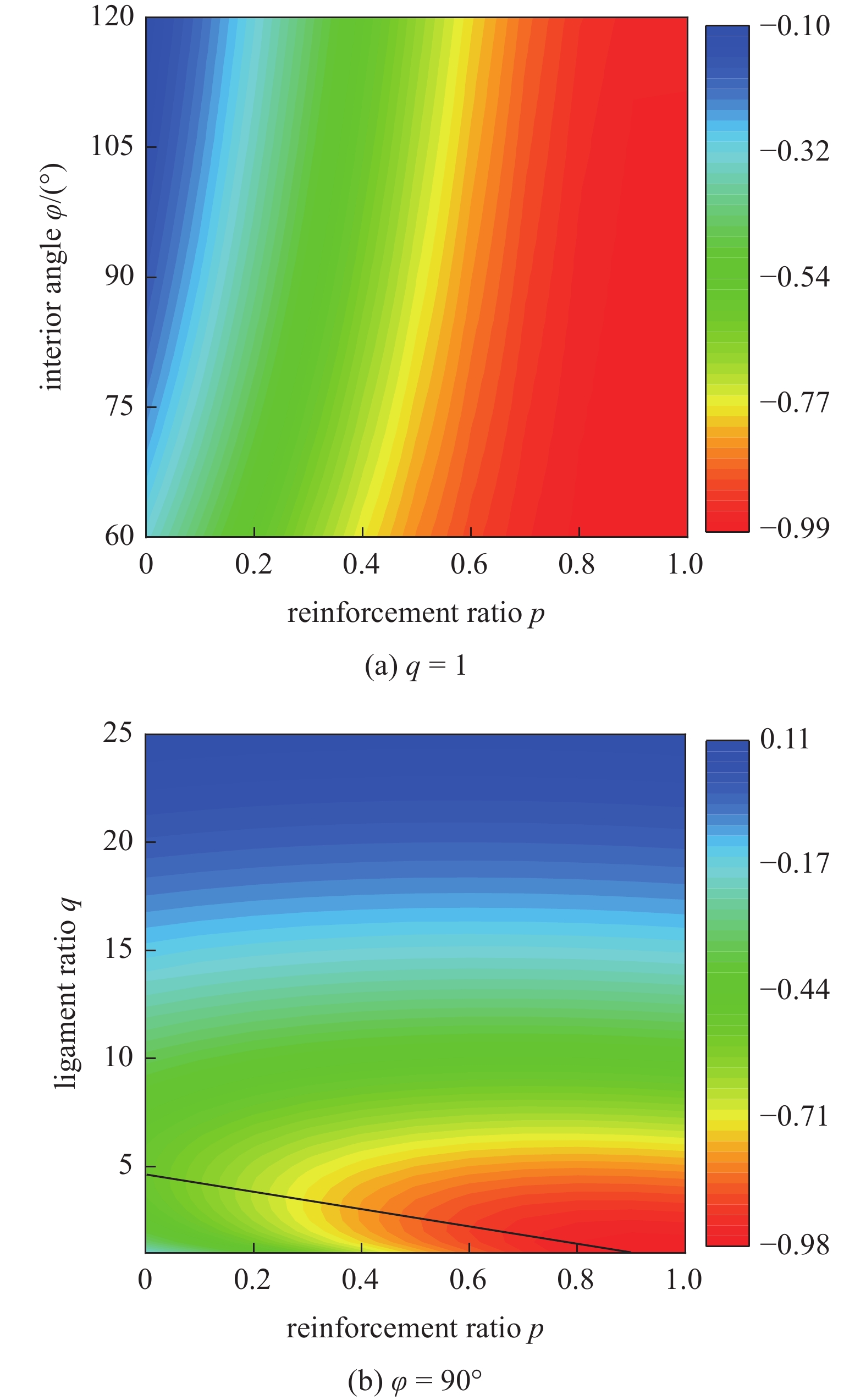
为了直观地研究几何参数对增强六手臂缺失支柱手性拉胀材料宏观力学性能的影响, 图11和12分别给出了等效泊松比和弹性模量随手臂和中心绑扎桁架夹角
$ \varphi $ , 增强率p及手臂比q变化的云图.![]() 图 11 结构等效泊松比云图Figure 11. Contour plots the effective Poisson’s ratio over a wide range
图 11 结构等效泊松比云图Figure 11. Contour plots the effective Poisson’s ratio over a wide range由图11和图12可见, 改进的拉胀结构可以提供在大范围可调的泊松比(−1到0)和弹性模量. 由图11(a)可知: (1)结构的拉胀效应随着“Z”型手臂内角的增大而减弱, 这是由于内角的增大意味着长手臂和中心绑扎桁架的连结处刚度减弱, 抑制了中心绑扎桁架的旋转效应; (2)由于中心绑扎桁架的刚性随增强率的增加而增强, 结构的拉胀效应随着增强率的增大而增强. 但由图8(b)可知, 拉胀效应与手臂比的关系是非单调的, 表现出两个阶段的演变, 在第一阶段(q达到阈值之前, 图11(b)中黑色线表示), 手臂比越大拉胀效应越强, 第二阶段则相反. 这是因为q越大意味着外手臂相对中心绑扎桁架越强, 因而更容易触发结构的旋转效应, 具有更好的拉胀效应. 但q持续增大时, 结构逐渐趋于三角形网络结构, 不具有拉胀特性. 因此, 结构的泊松比演化和q的关系表现出了两阶段的特征.
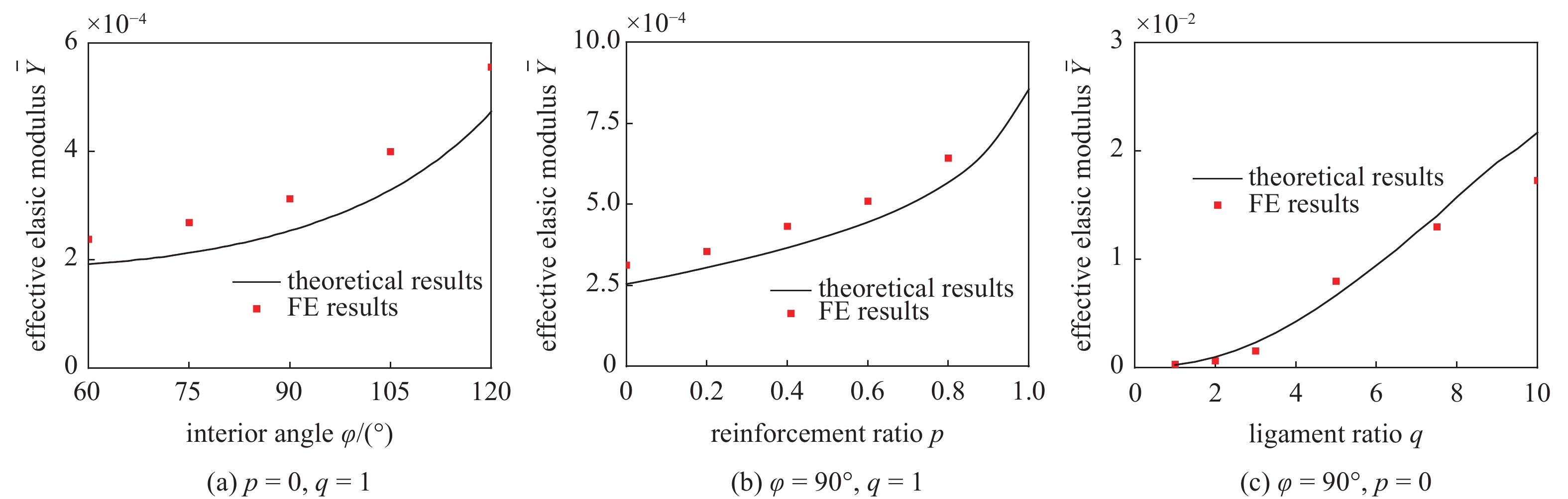
由图12可知, 结构的弹性模量随着夹角、增强率和手臂比的增大而单调增大.
![]() 图 12 结构等效弹性模量云图Figure 12. Contour plots the effective elastic modulus over a wide range
图 12 结构等效弹性模量云图Figure 12. Contour plots the effective elastic modulus over a wide range3.2 有限元结果对比
本节进一步将等效泊松比和弹性模量的理论解析结果与有限元计算结果进行了比较.
有限元计算采用ABAQUS软件完成. 计算时设定如下: (1)基体材料弹性模量和泊松比分别为1和0.3; (2)单元类型为CPE4四节点平面应变单元; (3)根据网格收敛性分析, 网格尺寸为0.25t, 即: 保证沿梁厚度方向至少有4个单元; (4)由于第2章的理论推导是在线弹性小变形下开展的, 本节的有限元计算也局限为线弹性小变形分析; (5)计算针对单一元胞结构展开, 为消除边界条件的影响, 对元胞结构施加了周期性边界条件(详见附录B).
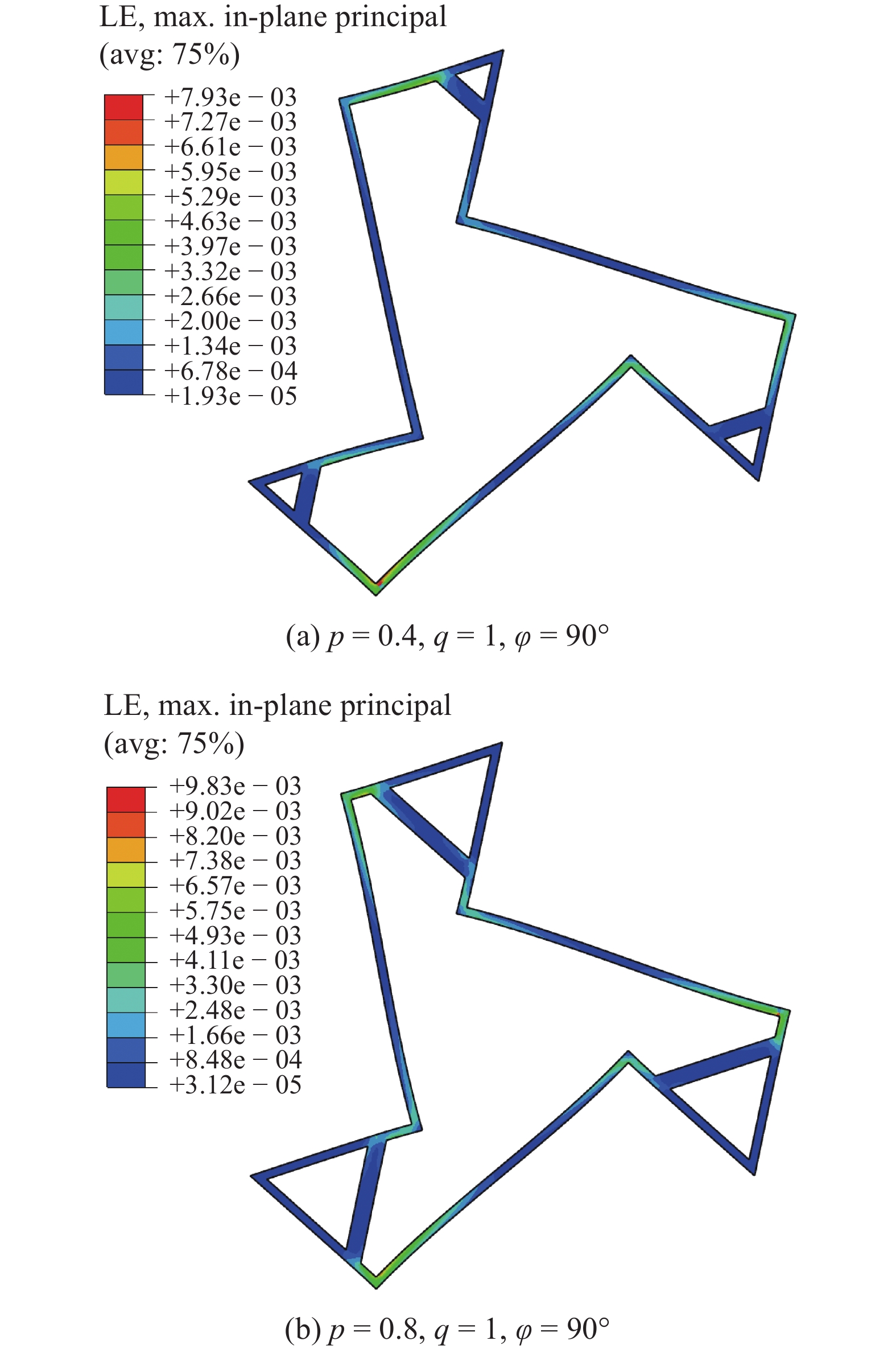
图13给出了变形较大时(等效应变为5%)不同几何参数最小代表单元的最大面内主应变云图. 由图可见, 结构整体变形较大时, 各部件的局部变形相对很小, 验证了假定(4)的合理性. 另外, 图13还表明, 结构的三角形元素部分的应变很小, 也说明了理论推导时将其假定为刚体部件的合理性.
![]() 图 13 等效应变为5%时最小代表单元最大面内主应变云图Figure 13. Contour plots the maximum in-plane principal strain of the smallest repeated units at an effective strain of 5%
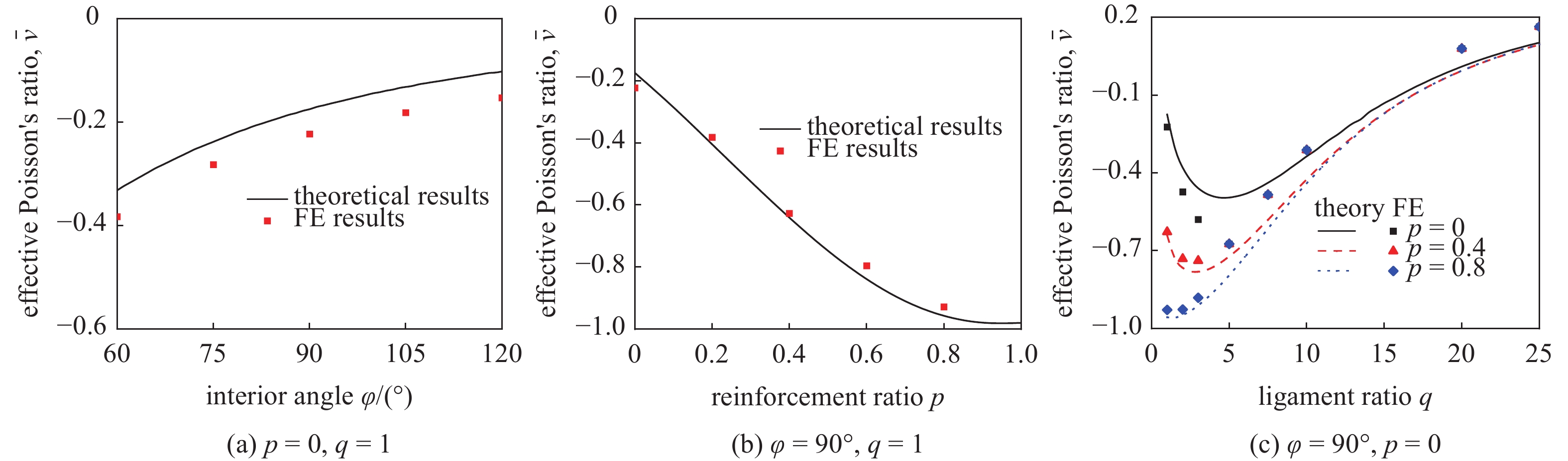
图 13 等效应变为5%时最小代表单元最大面内主应变云图Figure 13. Contour plots the maximum in-plane principal strain of the smallest repeated units at an effective strain of 5%图14和图15为不同几何尺寸下, 结构等效泊松比和弹性模量的理论值与有限元结果. 显然, 两种结果吻合的较好.
![]() 图 14 不同几何参数下结构等效泊松比的理论和有限元模拟结果对比图Figure 14. Theoretical and FE results of the effective Poisson’s ratio of the enhanced hexa-missing rib auxetic honeycomb over a range
图 14 不同几何参数下结构等效泊松比的理论和有限元模拟结果对比图Figure 14. Theoretical and FE results of the effective Poisson’s ratio of the enhanced hexa-missing rib auxetic honeycomb over a range需要指出的是, 本文的理论解是基于将最小代表单元的三角形部分假定为刚体这一假设而推导的. 在结构受载时, 三角形部分不可避免地也会产生变形(并且其变形的程度受结构相对尺寸的影响), 这部分变形同样也会对结构总变形能做贡献. 另外, 理论解中将实体结构简化为梁, 所有与长度相关的尺寸均为各梁段中性轴的长度. 但事实上实体结构的结果与梁的结果也会有偏差. 理论模型的精度及误差主要源自上述两个因素, 并且这两个因素对理论值的影响并不同向, 会存在竞争关系. 因此, 图14和15中部分理论结果比有限元结果大, 而另一部分比有限元结果小.
![]() 图 15 不同几何参数下结构等效弹性模量的理论和有限元模拟结果对比图Figure 15. Theoretical and FE results of the effective elastic modulus of the enhanced hexa-missing rib auxetic honeycomb over a range
图 15 不同几何参数下结构等效弹性模量的理论和有限元模拟结果对比图Figure 15. Theoretical and FE results of the effective elastic modulus of the enhanced hexa-missing rib auxetic honeycomb over a range4. 结 论
基于能量法, 本文首先在小变形框架下推导了前期研究工作中发展的增强六手臂缺失支柱手性拉胀超材料的等效力学性能参数的理论模型. 研究表明, 只有在微结构具有特定几何参数时, 增强六手臂缺失支柱手性拉胀超材料的等效泊松比和弹性模量才有简洁的理论表达式. 因此, 为便于理论模型的应用, 本文进而开发了MATLAB图形用户界面, 只需输入几何参数就可以方便地直接获取相应结构的等效力学性能参数. 最后, 系统讨论了关键几何参数对结果力学性能的影响规律.
需要指出的是, 本文的研究局限于理论推导和有限元分析. 在后续的工作中, 作者拟开展系统的实验研究来考察增强六手臂缺失支柱手性拉胀超材料的静/动态力学性能.
附录A
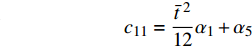
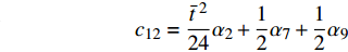
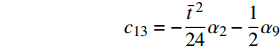
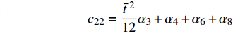
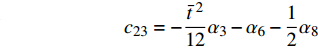
$$ {\boldsymbol{ K}} = \left[ {\begin{array}{*{20}{c}} {\dfrac{{{t^2}}}{6}{\alpha _1} + 2{\alpha _5}{L_0}^2}&{\dfrac{{{t^2}}}{{12{L_0}}}{\alpha _2} + {\alpha _7}{L_0} + {\alpha _9}{L_0}}&{ - \dfrac{{{t^2}}}{{12{L_0}}}{\alpha _2} - {\alpha _9}{L_0}} \\ {\dfrac{{{t^2}}}{{12{L_0}}}{\alpha _2} + {\alpha _7}{L_0} + {\alpha _9}{L_0}}&{\dfrac{{{t^2}}}{{6{L_0}^2}}{\alpha _3} + 2{\alpha _4} + 2{\alpha _6} + 2{\alpha _8}}&{ - \dfrac{{{t^2}}}{{6{L_0}^2}}{\alpha _3} - 2{\alpha _6} - {\alpha _8}} \\ { - \dfrac{{{t^2}}}{{12{L_0}}}{\alpha _2} - {\alpha _9}{L_0}}&{ - \dfrac{{{t^2}}}{{6{L_0}^2}}{\alpha _3} - 2{\alpha _6} - {\alpha _8}}&{\dfrac{{{t^2}}}{{6{L_0}^2}}{\alpha _3} + 2{\alpha _6}} \end{array}} \right] $$ $$ {\boldsymbol{C}} = \left[ {\begin{array}{*{20}{c}} {{c_{11}}}&{{c_{12}}}&{{c_{13}}} \\ {{c_{12}}}&{{c_{22}}}&{{c_{23}}} \\ {{c_{13}}}&{{c_{23}}}&{{c_{33}}} \end{array}} \right] $$ 其中
$$ {c_{11}} = \frac{{{{\bar t}^{\;2}}}}{{12}}{\alpha _1} + {\alpha _5} $$ $$ {c_{12}} = \frac{{{{\bar t}^{\;2}}}}{{24}}{\alpha _2} + \frac{1}{2}{\alpha _7} + \frac{1}{2}{\alpha _9} $$ $$ {c_{13}} = - \frac{{{{\bar t}^{\;2}}}}{{24}}{\alpha _2} - \frac{1}{2}{\alpha _9}\qquad $$ $$ {c_{21}} = {c_{12}} \qquad\qquad\qquad\qquad\quad $$ $${c_{22}} = \frac{{{{\bar t}^{\;2}}}}{{12}}{\alpha _3} + {\alpha _4} + {\alpha _6} + {\alpha _8} $$ $$ {c_{23}} = - \frac{{{{\bar t}^{\;2}}}}{{12}}{\alpha _3} - {\alpha _6} - \frac{1}{2}{\alpha _8} $$ $${c_{31}} = {c_{13}}\qquad\qquad\qquad\qquad\quad $$ $${c_{32}} = {c_{23}}\qquad\qquad\qquad\qquad\quad $$ $$ {c_{33}} = \frac{{{{\bar t}^{\;2}}}}{{12}}{\alpha _3} + {\alpha _6} $$ 直臂结构曲线描述方程
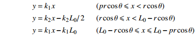
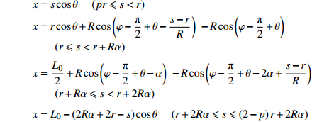
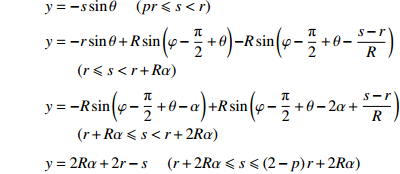
$$ {\begin{array}{*{20}{l}} {y = {k_1}x} \\ {y = {k_2}x - {{{k_2}{L_{\text{0}}}} \mathord{\left/ {\vphantom {{{k_2}{L_{\text{0}}}} 2}} \right. } 2}} \\ {y = {k_1}x - {k_1}{L_{\text{0}}}} \end{array}} {\text{ }}\begin{array}{*{20}{l}} {(pr\cos \theta \leqslant x < r\cos \theta )} \\ {(r\cos \theta \leqslant x < {L_0} - r\cos \theta )} \\ {({L_0} - r\cos \theta \leqslant x \leqslant {L_0} - pr\cos \theta )} \end{array} $$ 曲臂结构曲线描述方程
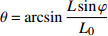
其中,
$ {k_1} = \tan \theta $ ,$ {k_2} = \tan \left( {\varphi + \theta } \right) $ ,$\theta = \arcsin \dfrac{{L\sin \varphi }}{{{L_0}}}$ ,${L_0} = 2\sqrt {{{\left( {{L \mathord{\left/ {\vphantom {L 2}} \right. } 2}} \right)}^2} + {r^2} - rL\cos \varphi }.$ .$$ \begin{array}{l} x = s\cos \theta {\text{ }}\quad (pr \leqslant s < r) \\ x = r\cos \theta + R\cos \left( {\varphi - \dfrac{{\text{π}} }{2} + \theta - \dfrac{{s - r}}{R}} \right) {\text{ }} - R\cos \left( {\varphi - \dfrac{{\text{π}} }{2} + \theta } \right){\text{ }}\\ \qquad (r \leqslant s < r + R\alpha ) \\ x = \dfrac{{{L_0}}}{2} + R\cos \left( {\varphi - \dfrac{{\text{π}} }{2} + \theta - \alpha } \right) {\text{ }} - R\cos \left( {\varphi - \dfrac{{\text{π}} }{2} + \theta - 2\alpha + \dfrac{{s - r}}{R}} \right){\text{ }}\\ \qquad(r + R\alpha \leqslant s < r + 2R\alpha ) \\ x = {L_0} - \left( {2R\alpha + 2r - s} \right)\cos \theta {\text{ }}\quad (r + 2R\alpha \leqslant s \leqslant \left( {2 - p} \right)r + 2R\alpha ) \end{array} $$ $$ \begin{array}{l} y = - s\sin \theta {\text{ }}\quad (pr \leqslant s < r) \\ y = - r\sin \theta + R\sin \left( {\varphi - \dfrac{{\text{π}} }{2} + \theta } \right) {{ - }}R\sin \left( {\varphi - \dfrac{{\text{π}} }{2} + \theta - \dfrac{{s - r}}{R}} \right){\text{ }}\\ \qquad (r \leqslant s < r + R\alpha ) \\ y = - R\sin \left( {\varphi - \dfrac{{\text{π}} }{2} + \theta - \alpha } \right) {{ + }}R\sin \left( {\varphi - \dfrac{{\text{π}} }{2} + \theta - 2\alpha + \dfrac{{s - r}}{R}} \right){\text{ }}\\ \qquad (r + R\alpha \leqslant s < r + 2R\alpha ) \\ y = {2R\alpha + 2r - s} {\text{ }}\quad (r + 2R\alpha \leqslant s \leqslant \left( {2 - p} \right)r + 2R\alpha ) \end{array} $$ 附录B
为简化计算, 本文的分析只针对单一元胞结构, 采用基于ABAQUS软件的有限元均匀化方法来考察手性拉胀材料的等效力学行为. 为消除边界条件的影响, 计算时对元胞结构施加了周期性边界条件[52-53], 即
$$ \tag{B1} {{\boldsymbol{x}}^ + } - {{\boldsymbol{x}}^ - } = \bar{\boldsymbol{ F}}\left( {{{\boldsymbol{X}}^ + } - {{\boldsymbol{X}}^ - }} \right),{\text{ }}{{\boldsymbol{t}}^ + } = - {{\boldsymbol{t}}^ - } $$ 式中,
$ {{\boldsymbol{x}}^ \pm } $ 和$ {{\boldsymbol{X}}^ \pm } $ 分别为对应边界的空间和参考坐标;${{\boldsymbol{t}}^ \pm } = {{\boldsymbol{P}}^ \pm }{{\boldsymbol{N}}^ \pm }$ 代表外法向为$ {{\boldsymbol{N}}^ \pm } $ 边界上节点的牵拉应力($ {\boldsymbol{P}} $ 为第一类皮奥拉−基尔霍夫(Piola-Kirchhoff)应力). 等效变形梯度$ \bar{\boldsymbol{ F}} $ 及等效第一类皮奥拉−基尔霍夫应力可表示为$$ \tag{B2} \bar{\boldsymbol{ F}} = \left\langle {\boldsymbol{F}} \right\rangle = \frac{1}{{{V_0}}}\int_{{V_0}} {{\boldsymbol{F}}{{\rm{d}}} V} = \frac{1}{{{V_0}}}\int_{\partial {V_0}} {{\boldsymbol{x}} \otimes {\boldsymbol{N}}{{\rm{d}}} S} $$ $$ \tag{B3} \bar{\boldsymbol{ P}} = \left\langle {\boldsymbol{P}} \right\rangle = \frac{1}{{{V_0}}}\int_{{V_0}} {{\boldsymbol{P}}{{\rm{d}}} V} = \frac{1}{{{V_0}}}\int_{\partial {V_0}} {{\boldsymbol{t}} \otimes {\boldsymbol{X}}{{\rm{d}}} S} $$ 式(B2)和式(B3)中,
$ {V_0} $ 和$ \partial {V_0} $ 分别为元胞在参考坐标系下的体积和边界.元胞的整体变形可由等效Biot应变[54]来度量, 即
$$ \tag{B4} \bar{ {\textit{Ξ}}}{\text{ = }}\sqrt {{{\bar{\boldsymbol{ F}}}^{\text{T}}}\bar{\boldsymbol{ F}}} - {{\boldsymbol{1}}} $$ 其中,
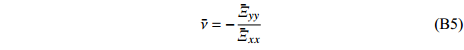
$ {{\boldsymbol{1}}} $ 为二阶单位张量.等效泊松比可定义为
$$ \tag{B5} \bar \nu = - \frac{{{{{{\bar {{\textit{Ξ}}} }}}_{yy}}}}{{{{{{\bar {{\textit{Ξ}}} }}}_{xx}}}} $$ 图B1给出了特定结构尺寸下(p = 0.6, q = 1,
$ \varphi = {90^ \circ } $ )对一个单胞施加周期性边界条件以及对阵列结构(含n × n个单胞)直接建模所得的等效泊松比结果的对比. 由图可见, 随着n (n为阵列结构中完整单胞的数目)的增加, 阵列结构直接建模的计算结果将收敛于周期性边界条件获得的结果, 验证了周期性边界条件结果的准确性.![]() B1 对一个单胞施加周期性边界条件以及对阵列结构(包含n × n 单胞)直接建模所得泊松比对比图 (p = 0.6, q = 1,
B1 对一个单胞施加周期性边界条件以及对阵列结构(包含n × n 单胞)直接建模所得泊松比对比图 (p = 0.6, q = 1,$ \varphi = {90^ \circ } $ )B1. The effective Poisson’s ratio obtained by the PBCs-based homogenization method and calculated from lattice structures consisting of n × n unit-cell array (p = 0.6, q = 1,$ \varphi = {90^ \circ } $ ) -
![]()
图 1 传统手性拉胀材料: (a) 三手臂; (b) 反三手臂; (c) 四手臂; (d) 反四手臂; (e) 六手臂
Figure 1. (a) Tri-, (b) anti-tri-, (c) tetra-, (d) anti-tetra-, (e) hexa-chiral honeycombs
![]()
图 2 缺失支柱手性拉胀材料: (a) 三手臂; (b) 反三手臂; (c) 四手臂; (d) 反四手臂; (e) 六手臂
Figure 2. (a) Tri-, (b) anti-tri-, (c) tetra-, (d) anti-tetra-, (e) hexa-missing rib honeycombs
![]()
图 4 (a) 阵列结构受远程应力示意图; (b) 最小代表单元受力图;(c) 等效最小代表单元
Figure 4. (a) Schematic diagram of an enhanced hexa-missing rib lattice under far field uniaxial loading. (b) The related free boundary diagram of the smallest repeated unit. (c) The effective smallest repeated unit
![]()
图 5 任意欧拉−伯努利梁结构受力图
Figure 5. Force diagram of an Euler–Bernoulli beam with arbitrary shape
![]()
图 6 最小代表单元各“Z”型梁受力图
Figure 6. Force diagram of the zigzag ligaments of the smallest repeated unit
![]()
图 7 元胞中心节点区受力图
Figure 7. Force diagram of an area surrounding the central point of the unit-cell
![]()
图 8 最小代表单元变形示意图
Figure 8. Schematic diagram of the deformation of smallest repeated unit
![]()
图 9 (a) 直臂与 (b) 曲臂结构计算模型
Figure 9. Calculation diagram of the enhanced hexa-missing rib auxetic honeycombs with (a) straight ligament and (b) wavy ligament
![]()
图 10 图形用户界面: (a) 直臂结构计算和(b) 曲臂结构计算
Figure 10. Graphical user interface: (a) calculation of auxetics with straight ligaments and (b) calculation of auxetics with wavy ligaments
![]()
图 11 结构等效泊松比云图
Figure 11. Contour plots the effective Poisson’s ratio over a wide range
![]()
图 12 结构等效弹性模量云图
Figure 12. Contour plots the effective elastic modulus over a wide range
![]()
图 13 等效应变为5%时最小代表单元最大面内主应变云图
Figure 13. Contour plots the maximum in-plane principal strain of the smallest repeated units at an effective strain of 5%
![]()
图 14 不同几何参数下结构等效泊松比的理论和有限元模拟结果对比图
Figure 14. Theoretical and FE results of the effective Poisson’s ratio of the enhanced hexa-missing rib auxetic honeycomb over a range
![]()
图 15 不同几何参数下结构等效弹性模量的理论和有限元模拟结果对比图
Figure 15. Theoretical and FE results of the effective elastic modulus of the enhanced hexa-missing rib auxetic honeycomb over a range
![]()
B1 对一个单胞施加周期性边界条件以及对阵列结构(包含n × n 单胞)直接建模所得泊松比对比图 (p = 0.6, q = 1,
$ \varphi = {90^ \circ } $ )B1. The effective Poisson’s ratio obtained by the PBCs-based homogenization method and calculated from lattice structures consisting of n × n unit-cell array (p = 0.6, q = 1,
$ \varphi = {90^ \circ } $ ) -
[1] 吴文旺, 肖登宝, 孟嘉旭等. 负泊松比结构力学设计、抗冲击性能及在车辆工程应用与展望. 力学学报, 2021, 53(3): 611-638 (Wu Wenwang, Xiao Dengbao, Meng Jiaxu, et al. Mechanical design, impact energy absorption and applications of auxetic structures in automobile lightweight engineering. Chinese Journal of Theoretical and Applied Mechanics, 2021, 53(3): 611-638 (in Chinese) doi: 10.6052/0459-1879-20-333 [2] 任鑫, 张相玉, 谢亿民. 负泊松比材料和结构的研究进展. 力学学报, 2019, 51(3): 656-687 (Ren Xin, Zhang Xiangyu, Xie Yimin. Research progress in auxetic materials and structures. Chinese Journal of Theoretical and Applied Mechanics, 2019, 51(3): 656-687 (in Chinese) [3] Zhu Y, Jiang S, Lu F, et al. A novel enhanced anti-tetra-missing rib auxetic structure with tailorable in-plane mechanical properties. Engineering Structures, 2022, 262: 114399 doi: 10.1016/j.engstruct.2022.114399
[4] Duan S, Xi L, Wen W, et al. Mechanical performance of topology-optimized 3D lattice materials manufactured via selective laser sintering. Composite Structures, 2020, 238: 111985 doi: 10.1016/j.compstruct.2020.111985
[5] Zhu Y, Luo Y, Gao D, et al. In-plane elastic properties of a novel re-entrant auxetic honeycomb with zigzag inclined ligaments. Engineering Structures, 2022, 268: 114788 doi: 10.1016/j.engstruct.2022.114788
[6] Ren X, Das R, Tran P, et al. Auxetic metamaterials and structures: a review. Smart Materials and Structures, 2018, 27(2): 023001 doi: 10.1088/1361-665X/aaa61c
[7] Logakannan KP, Ramachandran V, Rengaswamy J, et al. Numerical study of a re-entrant diamond structure under dynamic compression. IOP Conference Series:Materials Science and Engineering, 2021, 1067: 012109 doi: 10.1088/1757-899X/1067/1/012109
[8] Wu W, Hu W, Qian G, et al. Mechanical design and multifunctional applications of chiral mechanical metamaterials: A review. Materials & Design, 2019, 180: 107950
[9] Wang Z, Hu H. Auxetic materials and their potential applications in textiles. Textile Research Journal, 2014, 184(15): 1600-1611
[10] Zhao X, Wei L, Wen D, et al. Bending response and energy absorption of sandwich beams with novel auxetic honeycomb core. Engineering Structures, 2021, 247: 113204 doi: 10.1016/j.engstruct.2021.113204
[11] Novak N, Krstulović-Opara L, Ren Z, et al. Mechanical properties of hybrid metamaterial with auxetic chiral cellular structure and silicon filler. Composite Structures, 2020, 234: 111718 doi: 10.1016/j.compstruct.2019.111718
[12] Alex R. Development and performance evaluation of large-scale auxetic protective systems for localised impulsive loads. International Journal of Protective Structures, 2019, 10(3): 390-417 doi: 10.1177/2041419619858087
[13] Qi Ch, Remennikov A, Pei LZ, et al. Impact and close-in blast response of auxetic honeycomb-cored sandwich panels: Experimental tests and numerical simulations. Composite Structures, 2017, 180: 161-178 doi: 10.1016/j.compstruct.2017.08.020
[14] Chen G, Zhang P, Deng N, et al. Paper tube-guided blast response of sandwich panels with auxetic re-entrant and regular hexagonal honeycomb cores—An experimental study. Engineering Structures, 2022, 253: 113790 doi: 10.1016/j.engstruct.2021.113790
[15] Han SC, Kang DS, Kang K, et al. Two nature-mimicking auxetic materials with potential for high energy absorption. Materials Today, 2019, 26(5): 30-39
[16] 张相闻. 船舶宏观负泊松比效应蜂窝减振及防护结构设计方法研究. [博士论文]. 上海: 上海交通大学, 2017 Zhang Xiangwen. Research on design methods of auxetic cellular structures for vibration reduction and defensive structures of ships. [PhD Thesis]. Shanghai: Shanghai Jiao Tong University, 2017 (in Chinese)
[17] Paul M, Alderson A, Jordan-Mahy N, et al. The use of auxetic materials in tissue engineering. Biomaterials Science, 2020, 8(8): 2074-2083
[18] Kolken HMA, Lietaert K, Van der Sloten T, et al. Mechanical performance of auxetic meta-biomaterials. Journal of the Mechanical Behavior of Biomedical Materials, 2020, 104: 103658 doi: 10.1016/j.jmbbm.2020.103658
[19] Jang B, Won S, Kim J, et al. Auxetic meta-display: stretchable display without image distortion. Advanced Functional Materials, 2022, 32: 2113299
[20] Xu Y, Schlangen E, Luković M, et al. Tunable mechanical behavior of auxetic cementitious cellular composites (CCCs): Experiments and simulations. Construction and Building Materials, 2021, 266: 121388
[21] Zhang X, Ren X, Wang X, et al. A novel combined auxetic tubular structure with enhanced tunable stiffness. Composites: Part B, Engineering, 2021, 266: 109303
[22] Zhang Y, Ren X, Zhang X, et al. A novel buckling-restrained brace with auxetic perforated core: Experimental and numerical studies. Engineering Structures, 2021, 249: 113223 doi: 10.1016/j.engstruct.2021.113223
[23] Jiang Y, Liu Z, Matsuhisa N, et al. Auxetic mechanical metamaterials to enhance sensitivity of stretchable strain sensors. Advanced Materials, 2018, 30(12): 1706589 doi: 10.1002/adma.201706589
[24] Maria LDB, Andrea B. Auxetic behavior and acoustic properties of microstructured piezoelectric strain sensors. Smart Materials and Structures, 2017, 26(8): 085037 doi: 10.1088/1361-665X/aa7772
[25] Pan Q, Chen S, Chen F, et al. Programmable soft bending actuators with auxetic metamaterials. Science China: Technological Sciences, 2020, 63(12): 2518-2526 doi: 10.1007/s11431-020-1741-2
[26] Kelkar PU, Kim HS, Cho KH, et al. Cellular auxetic structures for mechanical metamaterials: A review. Sensors, 2020, 20: 3132
[27] Navier. Resume des lecons Donnees A L'Ecole des Ponts et Chaussees Sur L'Application de la Mecanique A L'Etablissement des Constructions et des MacHines. Charleston: BiblioBazaar, 2010: 482 (in French)
[28] Evans KE. Auxetic polymers—a new range of materials. Endeavour, 1991, 15(4): 170-174 doi: 10.1016/0160-9327(91)90123-S
[29] Wang Z, Luan C, Liao G, et al. Progress in auxetic mechanical metamaterials: structures, characteristics, manufacturing methods, and applications. Advanced Engineering Materials, 2020, 22(10): 2000312 doi: 10.1002/adem.202000312
[30] Luo C, Han C, Zhang X, et al. Design, manufacturing and applications of auxetic tubular structures: A review. Thin-Walled Structures, 2021, 163: 107682 doi: 10.1016/j.tws.2021.107682
[31] Matthew W, Muhammad FK, Mahdi B, et al. On the design workflow of auxetic metamaterials for structural applications. Smart Materials and Structures, 2022, 31(2): 023002 doi: 10.1088/1361-665X/ac3f78
[32] Ghavidelnia N, Bodaghi M, Hedayati R, et al. Idealized 3D auxetic mechanical metamaterial: An analytical, numerical, and experimental study. Materials, 2021, 14(4): 1-36
[33] Jiang Y, Li Y. 3D printed chiral cellular solids with amplified auxetic effects due to elevated internal rotation. Advanced Engineering Materials, 2017, 19(2): 1600609 doi: 10.1002/adem.201600609
[34] Jiang Y, Li Y. 3D printed auxetic mechanical metamaterial with chiral cells and re-entrant cores. Scientific Reports, 2018, 8(1): 2397 doi: 10.1038/s41598-018-20795-2
[35] Zhu Y, Wang ZP, Poh LH. Auxetic hexachiral structures with wavy ligaments for large elasto-plastic deformation. Smart Materials and Structures, 2018, 27(5): 055001 doi: 10.1088/1361-665X/aab33d
[36] Zhu Y, Zeng Z, Wang ZP, et al. Hierarchical hexachiral auxetics for large elasto-plastic deformation. Materials Research Express, 2019, 6(8): 085701 doi: 10.1088/2053-1591/ab1a22
[37] Pozniak AA, Wojciechowski KW. Poisson's ratio of rectangular anti-chiral structures with size dispersion of circular nodes. Physica Status Solidi B-Basic Solid State Physics, 2014, 251(2): 367-374 doi: 10.1002/pssb.201384256
[38] Mizzi L, Attard D, Gatt R, et al. Influence of translational disorder on the mechanical properties of hexachiral honeycomb systems. Composites Part B:Engineering, 2015, 80: 84-91 doi: 10.1016/j.compositesb.2015.04.057
[39] Alderson A, Alderson KL, Attard D. Elastic constants of 3-, 4- and 6-connected chiral and anti-chiral honeycombs subject to uniaxial in-plane loading. Composites Science and Technology, 2010, 70(7): 1042-1048 doi: 10.1016/j.compscitech.2009.07.009
[40] Zhang K, Zhao P, Zhao C, et al. Study on the mechanism of band gap and directional wave propagation of the auxetic chiral lattices. Composite Structures, 2020, 238: 111952 doi: 10.1016/j.compstruct.2020.111952
[41] Lu X, Tan VBC, Tay TE. Auxeticity of monoclinic tetrachiral honeycombs. Composite Structures, 2020, 241: 112067 doi: 10.1016/j.compstruct.2020.112067
[42] Smith CW, Gaspar N, Ren XJ. Novel honeycombs with auxetic behavior. Acta Materialia, 2005, 53(8): 2439-2445 doi: 10.1016/j.actamat.2005.02.006
[43] Liu J, Zhang Y. Soft network materials with isotropic negative Poisson's ratios over large strains. Soft Matter, 2018, 14(5): 693-703 doi: 10.1039/C7SM02052J
[44] Kumar D, Poh LH, Quek ST. Isogeometric shape optimization of missing rib auxetics with prescribed negative Poisson’s ratio over large strains using genetic algorithm. International Journal of Mechanical Sciences, 2021, 193: 106169 doi: 10.1016/j.ijmecsci.2020.106169
[45] Clausen A, Wang F, Jensen JS, et al. Topology optimized architectures with programmable poisson's ratio over large deformations. Advanced Materials, 2015, 27(37): 5523-5527 doi: 10.1002/adma.201502485
[46] Zhu Y, Jiang S, Li J, et al. Novel isotropic anti-tri-missing rib auxetics with prescribed in-plane mechanical properties over large deformations. International Journal of Applied Mechanics, 2021, 13(10): 2150115 doi: 10.1142/S1758825121501155
[47] Zhu Y, Jiang S, Poh LH, et al. Enhanced hexa-missing rib auxetics for achieving targeted constant NPR and in-plane isotropy at finite deformation. Smart Materials and Structures, 2020, 29(4): 045030 doi: 10.1088/1361-665X/ab7949
[48] Smith CW, Grima JN, Evans KE. A novel mechanism for generating auxetic behaviour in reticulated foams: missing rib foam model. Acta Materialia, 2000, 48(17): 4349-4356 doi: 10.1016/S1359-6454(00)00269-X
[49] Wang L, Liu HT. Parameter optimization of bidirectional reentrant auxetic honeycomb metamaterial based on genetic algorithm. Composite Structures, 2021, 267: 113915
[50] Liu HT, Wang L. Design 3D improved star-shaped honeycomb with different tip angles from 2D analytical star-shaped model. Composite Structures, 2022, 283: 115154
[51] Liu J, Zhang Y. A mechanics model of soft network materials with periodic lattices of arbitrarily shaped filamentary microstructures for tunable poisson's ratios. Journal of Applied Mechanics, 2018, 85(5): 1-17
[52] Kochmann DM, Venturini GN. Homogenized mechanical properties of auxetic composite materials in finite-strain elasticity. Smart Materials and Structures, 2013, 22(8): 084004 doi: 10.1088/0964-1726/22/8/084004
[53] Stéphane L, Stéphane B. Une Toolbox Abaqus pour le calcul de propriétés effectives de milieux hétérogènes//10 e colloque national en calcul des structures, Giens, France, 2011 (in French)
[54] Biot MA. XLIII. Non-linear theory of elasticity and the linearized case for a body under initial stress. The London, Edinburgh, and Dublin Philosophical Magazine and Journal of Science, 1939, 27(183): 468-489
-
期刊类型引用(1)
1. 丁怡,王意乐,孙莉杰,靳亚康,陈龙泉. 液滴润湿固体表面的移动接触线:从吸附到滑动. 力学学报. 2024(08): 2203-2211 .  本站查看
本站查看
其他类型引用(0)
 下载:
下载:


计量
- 文章访问数: 844
- HTML全文浏览量: 384
- PDF下载量: 160
- 被引次数: 1