
引 言
在涡激振动控制方面,通过附加小圆柱改变主圆柱周围流场进而控制其振动,是近年来较为成熟的方法之一.下文根据附加圆柱数量的不同对已有研究进行分述.
Muddapa和Patnaik[12]研究发现,在参数组合(雷诺数$Re = 100$、直径比d/D = 0.1、控制角$\theta$ = 120$^\circ$,无量纲转速$\alpha = 2.0$)条件下,主圆柱的脱涡受到完全抑制.李椿萱等[13]对附属小圆柱对主圆柱绕流的研究发现,不论小圆柱个数如何,总是存在一个最优的抑制区域.此时,涡街被完全抑制,阻力显著下降.Jiménez-González和Huera-Huarte[14]的实验结果表明(雷诺数$Re$ = 9.2×10$^{3}\sim$2.6×10$^{4}$、直径比d/D = 0.12、质量比$m^{ \ast }$ = 1.94、阻尼比$\zeta$ = 0.011 7,参数定义见1.2节),当$\theta$ = 160$^\circ$和G/D = 0.045时,涡激振动抑制效果最佳,圆柱振幅下降了66%;而当$\theta$ = 90$^\circ$时,控制圆柱对主圆柱的振动有促进作用.此外,与振幅不同,脱涡频率对小圆柱的位置并不敏感.Zhu和Gao[11]的数值结果表明(雷诺数$Re=3484$、 直径比d/D = 0.06、控制角为$\theta$ = 135$^\circ$、间隙比为G/D = 0.09),内向反转小圆柱向主圆柱边界层输入动量,使边界层分离延迟,分离点后移,抑制主圆柱振动;相反地,外向反转小圆柱使主圆柱的振幅增加.Korkischko和Meneghini[15]实验研究了雷诺数$Re$ = 1.6×10$^{3}$~7.5×10$^{4}$下两个小圆柱对主圆柱涡激振动的影响情况. 其中,质量比$m^{ \ast }$ = 1.8、阻尼比$\zeta$ = 0.01、直径比d/D = 0.06、间隙比G/D = 0.07、控制角$\theta$ = 90$^\circ$、无量纲转速$\alpha$ = 5~10. 研究结果表明,与无附加小圆柱工况相比,当$\alpha$ = 5~10时,圆柱的振幅下降超过了57%,且抑制出现在较大的折合流速范围内.
综上可知,已有文献多关注涡激振动抑制问题,控制圆柱位于主圆柱下游,而将控制圆柱置于主圆柱上游以促进涡激振动的研究较少.基于此,本文对在主圆柱上游对称布置两个控制小圆柱以增大涡激振动振幅进行数值模拟,并探讨其作用机理.
1 数值方法
1.1 控制方程
流固耦合的数值模拟采用浸入边界法[24],控制方程如下
其中,${{u}}$为速度,$t$为时间,$p$为压强,$_{ }\nu$为运动黏滞系数,$\nabla$为梯度算子,${{f}}$为附加体积力矢量,代表流固耦合边界条件.
对仅做横流向运动的刚性圆柱,其运动方程可以用下述方程来描述
其中,M为圆柱质量,c为结构阻尼,k为弹簧刚度系数,$F_y$为圆柱受到的横流向流体力. 方程采用标准的Newmark-$\beta$法求解.
1.2 参数取值
不同控制角下附加小圆柱对主圆柱涡激振动影响数值模拟参数如下.基于主圆柱直径的雷诺数为$Re = {UD}/ \nu = 100$,质量比为$m^ \ast = m/{m_{\rm f} } = 2.0$,其中M为圆柱质量,$m_{\rm f}$为等体积流体质量. 附加小圆柱对称布置于主圆柱的上游,选定的控制角范围为$\theta = 30^ \circ \sim 90^ \circ$,为圆柱圆心连线与来流方向的夹角,前驻点处,$\theta$ = 0$^ \circ$. 上、下侧小圆柱分别以逆时针和顺时针旋转(外向反转)为正.附加小圆柱与主圆柱的直径比为d/D = 0.125,间隙比为G/D = 0.125. 为使圆柱响应最大,将阻尼比设为$\zeta = 0$.三圆柱刚性连接,仅作横向振动. 计算域大小为$100D\times 100D$,如图1所示.为保证数值精度,在圆柱周围采用加密网格,加密区域为$8D\times 8D$,无量纲网格尺寸为$\Delta x/ D = \Delta y/D = 1 /64$.
图1
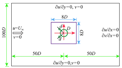
边界条件设置如下. 入口为Dirichlet型边界($u = U$,$v = 0)$,出口为Neumann型边界($\partial u/ \partial x = 0, \partial v/ \partial x = 0$,上下为可滑移边界($\partial u/ \partial y = 0, v = 0)$.此外,为保证数值收敛,需满足CFL条件,即$U_{max} \Delta t/ \Delta t/ \Delta x \le 0.5$,其中$U_{\max}$为流场中的最大流速.
2 程序验证
表1 单圆柱涡激振动结果对比
Table 1
3 结果和讨论
3.1 振动响应
为准确衡量主圆柱振动的平均振幅,涡激振动的无量纲振幅定义为$A^\ast= A/D = \sqrt{2} Y_{\rm rms}$[33],其中$Y_{\rm rms}$为横向振动位移的均方根值.
如图2所示,随着控制角的变化,圆柱响应呈现明显不同的规律. 当$\theta = 30^ \circ$时,主圆柱振动与单圆柱(无控制圆柱)情况相似,呈现出明显的初始分支和下端分支.但是,主圆柱振动的锁定区间($3.5 \le U_{\rm r} < 7.0)$要小于单圆柱的($3.5 \le U_{\rm r} < 8.5)$.此时,主圆柱的最大振幅($A^ * = 0.51)$也要比单圆柱的最大值($A^ * = 0.56)$小. 当$\theta = 45^ \circ \sim 60^ \circ$时,圆柱的振动呈现为初始分支和弛振分支.在初始分支,圆柱的振动由圆柱表面交替泄涡引起;在驰振分支,圆柱的振动由结构相对于来流的不对称性(考虑振动圆柱和来流的合速度)导致.驰振最显著的特点为圆柱振幅较大,且随着折合流速的增大而单调递增.两分支的临界折合流速随着控制角的增大而略有减小.$\theta = 45^ \circ$时临界折合流速为$U_{\rm r} = 5.5$,而$\theta = 60^ \circ$时,为$U_{\rm r} = 5.0$. 当$\theta = 75^ \circ \sim 90^ \circ$时,主圆柱的响应由初始分支和下降分支构成.在下降分支,振幅随着折合流速的增加而缓慢下降,且随着控制角的增大,振幅随着折合流速的下降趋势更加明显.值得注意的是,虽然圆柱振幅在折合流速较大时会出现下降,但是振幅仍明显大于单圆柱的情况.
图2
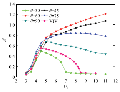
图2
不同控制角下圆柱振幅随折合流速变化情况
Fig.2
Vibration amplitude versus the reduced velocity under different control angles
总的来说,在初始分支,有、无附加小圆柱工况下圆柱的振幅几乎相等,圆柱的振动由交替泄涡控制.附加小圆柱对主圆柱涡激振动的影响主要出现在下端分支. 当$\theta = 30^ \circ$时,附加小圆柱对主圆柱振动起到抑制作用. 当$\theta = 45^ \circ \sim 60^ \circ$时,附加小圆柱对主圆柱振动起到促进作用,下端分支转变为弛振分支,圆柱的最大振幅分别为$A^ * = 1.08$ ($\theta$ = 45$^\circ$)和$A^ * = 1.22$ ($\theta$ = 60$^\circ$),比单圆柱工况分别大了93%和118%. 当$\theta = 75^ \circ \sim 90^ \circ$时,下端分支变为下降分支,振幅仍较大,介于驰振分支和下端分支之间.
为细致地确定最优控制角,本文采用较小的控制角增量,模拟了$\theta$ = 60$^\circ$附近圆柱振幅随控制角的变化情况.如图3所示,圆柱的最大振幅随着控制角的增加呈现出先增后减的趋势,最大振幅在$\theta = 60^ \circ$时获得.
图3
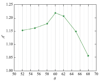
图3
当$U_{\rm r} = 11$时,圆柱振幅随控制角变化情况
Fig.3
Vibration amplitude varies with the control angle at$U_{\rm r}= 11$
3.2 流体力
为考察附加小圆柱对主圆柱涡激振动流体力的影响,图4给出了不同控制角下主圆柱流体力随折合流速变化情况.
图4
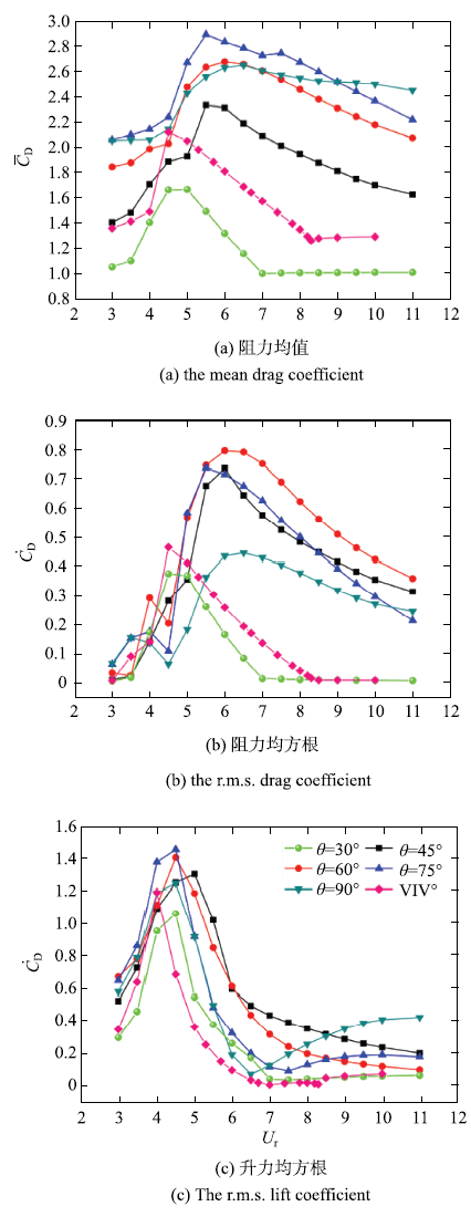
图4
不同控制角下流体力随折合流速变化情况
Fig.4
Fluid forces versus the reduced velocity at different control angles
如图4(a)所示,在有、无附加小圆柱的工况下,主圆柱受到的阻力均值均呈现出先增后减的趋势.总体来看,无附加圆柱工况下主圆柱的阻力均值要大于$\theta = 30^ \circ$的情况.主圆柱的阻力均值随着控制角的增大而增大,在$\theta$ = 75$^\circ$时达到最大,而在$\theta$ = 90$^\circ$略有下降.圆柱的阻力受两方面因素影响,一方面圆柱的大幅振动降低了圆柱的基底压强,提高了圆柱的阻力;另一方面,控制角较大时,控制圆柱增大了垂直来流方向的迎流面积,导致阻力增大.综合两个因素,主圆柱的阻力均值在$\theta$ = 75$^\circ$时达到最大,而非在主圆柱振幅最大的$\theta$ = 60$^\circ$.
如图4(b)所示,当$\theta = 30^ \circ$时主圆柱受到的阻力均方根与无附加小圆柱的情况类似,均表现为先增后减的趋势,最大值也均在$U_{\rm r} = 4.5$时取得. 当$\theta = 45^ \circ \sim 90^ \circ$时,主圆柱的阻力均方根呈现出"双峰"特征. 在$U_{\rm r}$ = 4.0附近出现第一个较小峰值,而在$U_{\rm r}$ = 6.0附近出现第二个较大峰值. 与无附加圆柱的情况相比,$\theta = 45^ \circ \sim 90^ \circ$工况的阻力均方根在较大折合流速时明显较大.
如图4(c)所示,有、无附加小圆柱的工况下,主圆柱受到的升力均方根较为相近,均呈现为先增后减的趋势,仅在$\theta = 75^ \circ \sim 90^ \circ$时,升力均方根在大折合流速时缓慢增加.各工况下,升力均方根的最大值均在$U_{\rm r} = 4.0 \sim 5.0$内取得.与主圆柱振幅相似,圆柱升力的均方根在$\theta = 45^ \circ \sim 75^ \circ$工况下较大.
3.3 旋涡脱落频率
为确定附加小圆柱对主圆柱旋涡脱落的影响,进一步研究不同控制角下旋涡脱落频率随折合流速变化的情况.如图5所示,当$\theta = 30^ \circ$时,主圆柱的脱涡频率随折合流速变化较小,在$St$ = 0.13 ~ 0.16范围内,其最小值($St = 0.13)$在$U_{\rm r} = 6.5$时取得.
图5
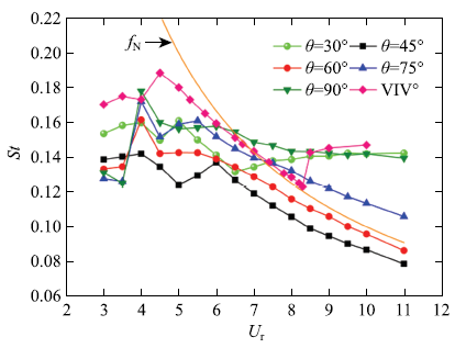
图5
不同控制角下主圆柱脱涡频率随折合流速变化情况
Fig.5
Vortex shedding frequency versus the reduced velocity at different control angles
对于$\theta = 45^ \circ \sim 90^ \circ$的工况,在折合流速较小时($U_{\rm r} < 6.0)$,脱涡频率随折合流速变化不规律. 在折合流速较大时($U_{\rm r} > 6.0)$,脱涡频率随折合流速增大而减小.大控制角的工况,下降的幅度明显较小.
对于无附加小圆柱的工况,在锁定区间内,旋涡脱落频率接近结构的自然频率$f_{\rm N}$,在锁定区间外,旋涡脱落频率与固定圆柱绕流的几乎相等.但在$\theta$ = 45$^\circ$~60$^\circ$工况下,大折合流速时,旋涡脱落频率一直与圆柱自然频率接近.也就是说,圆柱振动一直处于锁定状态,锁定区间没有上限.
3.4 作用机制
在附加小圆柱的影响下,主圆柱涡激振动出现明显的变化.其中,当控制角较小($\theta = 30^ \circ)$时,附加小圆柱对主圆柱振动呈现出明显的抑制作用;当控制角中等($\theta = 45^ \circ$$ \sim$$60^ \circ )$时,附加小圆柱对主圆柱振动则有显著的促进作用,此时主圆柱在折合流速较大时表现为弛振;之后,随控制角增加($\theta = 75^ \circ \sim 90^ \circ )$,促进作用逐渐下降. 为全面理解附加小圆柱的影响,本节结合主圆柱升力谱、升力与位移相位差、旋涡脱落时机、分离点变化、能量系数等,深入分析附加小圆柱的作用机制.
图6

图6
当$U_{\rm r} = 11.0$和$\theta = 30^ \circ$时,不同时刻下圆柱周围的涡量场(左)和压强场(右)
Fig.6
Vorticity fields (left) and pressure fields (right) around the circular cylinder at$U_{\rm r} = 11.0$ and$\theta = 30^ \circ$
图7
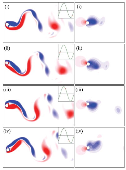
图7
当$U_{\rm r} = 11.0$和$\theta = 60^ \circ$时,不同时刻下圆柱周围涡量场(左)和压强场(右)
Fig.7
Vorticity fields (left) and pressure fields (right) around the circular cylinder at$U_{\rm r} = 11.0$ and$\theta = 60^ \circ$
图8
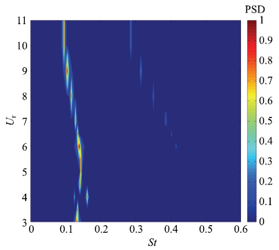
图8
当$\theta = 60^ \circ$时,主圆柱升力频谱随折合流速变化的情况
Fig.8
Lift spectra of the main cylinder versus the reduced velocity at$\theta = 60^ \circ$
图9
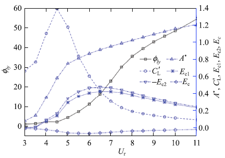
图9
当$\theta = 60^ \circ$时,主圆柱升力与位移的相位差($\phi _{ly} )$、升力均方根($C'_{\rm L} )$、振幅($A^ * )$以及能量系数($E_{\rm c1},E_{\rm c2},E_{\rm c}$分别为主圆柱、两附加小圆柱以及总能量系数)随折合流速变化情况
Fig.9
The phase difference between the lift and displacement ($\varphi _{ly} )$, the r.m.s. lift coefficient ($C'_{\rm L} )$, the vibration amplitude ($A^ * )$ of the main cylinder, and energy transfer coefficient ($E_{\rm c1}$,$E_{\rm c2}$,$E_{\rm c}$ denote the energy coefficients of the main, two small, and the sum of three cylinders, respectively.) in one period versus the reduced velocity at$\theta = 60^ \circ$
当$\theta = 60^ \circ$时,如图7所示,主圆柱从下向上运动(i)$ \to$(ii)的半个周期中,由于受到下侧剪切层的推挤,上侧剪切层堆积于主圆柱的上侧,此时一个明显的低压区形成于主圆柱的上侧,因此会对主圆柱的振动起到较大的促进作用.相同地,当主圆柱从上向下运动(iii)$ \to$(iv)的半个周期时,由于受到上侧剪切层的影响,下侧剪切层堆积于下半圆柱上,并形成一个明显的低压区,相应地也会对主圆柱的振动起到显著的促进作用.准稳态理论[35]指出弛振现象的出现来源于柱体两侧的不对称压力分布.压差越大,柱体振幅也就越大.对比图6可以看出,此时在主圆柱振动方向上产生的低压区范围更大,且压差更明显,相应地振幅也就更大.
为进一步解释主圆柱产生弛振的原因,本文从频率变化、主圆柱位移与升力相位差以及能量系数等角度展开如下分析.如图8所示,在整个折合流速范围内,主圆柱的升力均由基频主导,3倍频开始于$U_{\rm r} = 6.0$时,对应弛振开始的折合流速.随着折合流速的增大,倍频的能量逐渐增大.但是由于倍频对应的成分远低于基频,因此,倍频的出现对主圆柱振幅增大的作用有限.如图9所示,在涡振阶段($U_{\rm r} = 3.0 \sim 5.0)$,主圆柱升力与位移的相位差接近于零,从流体传递到振动主圆柱的能量也很小;而在弛振阶段($U_{\rm r} \ge 5.5)$,虽然主圆柱的升力均方根随折合流速有一定的下降,但升力与位移的相位差由接近0\r{ }迅速增加至55$^\circ$附近.由于升力对主圆柱做功的功率跟升力和振动速度有关,当两者同相位(升力与振动位移的相位差为90\r{ })时,流体输入到振动圆柱的功率最大.此外,采用Navrose和Mittal[36]建议的公式$E_{\rm c} = \int_0^T {C_{\rm L} (t)y'(t)} {\rm d}t = \left| {C_{\rm L} } \right|\left| {y'} \right|\sin \phi~(\phi$为升力与位移的相位差)得到了一个周期内由流体输入到柱体的能量系数,如图9所示,其中$E_{\rm c1},E_{\rm c2},E_{\rm c}$分别为主圆柱、两附加小圆柱以及系统的能量系数.由于本文模拟中阻尼比为零,因此,在一个完整的周期内,系统的能量系数($E_{\rm c})$应为零.也就是说,在圆柱系统运动的过程中,由流体向主圆柱传递的能量会在消耗在带动附加小圆柱的运动上.如图9所示,当折合流速较小时,主圆柱的能量系数较小,相应地附加小圆柱消耗的能量也较小;当进入弛振阶段后,主圆柱的能量系数则一直维持在较大值上,但当$U_{\rm r}>6.5$以后,由流体传递到主圆柱的能量系数下降,相应地附加小圆柱消耗的能量系数也减小.造成这种能量系数的下降可能与旋涡结构的变化有关,如图7所示,当系统处于弛振状态时,圆柱系统两侧的剪切层会直接从小圆柱上分离并最终形成旋涡.在此过程中,剪切层与附加小圆柱系统的相互作用较弱,能量消耗也就减小.相反,在涡振阶段,如图6所示,圆柱系统两侧的剪切层形成并从附加小圆柱上分离,但分离的剪切层会重附着于主圆柱上,产生二次相互作用,相应地使消耗的能量系数增加.
随着控制角的增大($\theta = 75^ \circ \sim 90^ \circ)$,附加小圆柱会使得剪切层的分离更加靠近圆柱的上下顶端,剪切层重附着区域也更加靠近主圆柱的底部,造成阻力增大,升力减小,与$\theta = 60^ \circ$的工况相比,减弱了对主圆柱振动的促进作用.如图10所示,当$\theta = 90^ \circ$时,由于附加小圆柱的存在,剪切层的分离出现在主圆柱正上和正下侧;当主圆柱从下向上运动(i)$\to$(ii)时,由于下侧剪切层排挤,使得上侧仅在很小的范围内附着于主圆柱的上半侧,更多的低压区产生于主圆柱的底部,因此,与$\theta = 60^ \circ$时相比,低压区产生的升力明显变小,对主圆柱的振动促进作用会显著下降.相同地,当主圆柱从上向下运动(iii)$ \to$(iv)时,受到上侧剪切层作用而堆积于主圆柱下半侧的低压区也要小一些,更多的低压区集中于圆柱的底部,因此,产生的促进作用也会较低.
图10
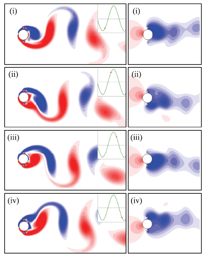
图10
当$U_{\rm r} = 11.0$和$\theta = 90^ \circ$时,不同时刻下圆柱周围涡量场(左)和压强场(右)
Fig.10
Vorticity fields (left) and pressure fields (right) around the circular cylinder at$U_{\rm r} = 11.0$ and$\theta = 90^ \circ$
总结起来,附加小圆柱的存在改变了主圆柱剪切层的分离点,影响了旋涡的形成和发展过程,起到了或促进或抑制主圆柱涡激振动的作用.
3.5 控制圆柱旋转速度的影响
本文进一步研究附加小圆柱的旋转速度对主圆柱涡激振动的影响.取无量纲转速为$\alpha =-2.0 \sim 2.0$,负值代表内向反转(IC),正值表示外向反转(OC).如图11所示,旋转的小圆柱无论内向反转还是外向反转均使主圆柱的振幅下降,其中内向反转时主圆柱振幅下降的幅度要大于外向反转的情况.这就是说,附加圆柱不旋转时对促进主圆柱振动更优.此外,旋涡的脱落频率几乎不受旋转速度的影响.
图11
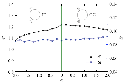
图11
不同转速下主圆柱振幅和脱涡频率的变化情况,其中$\theta = 60^ \circ$和$U_{\rm r} = 11.0$
Fig.11
Vibration amplitude and vortex shedding frequency versus the nondimensional rotation speed ($\alpha )$ with$\theta = 60^ \circ$ and$U_{\rm r} = 11.0$
4 结 论
通过在主圆柱上游对称布置两个控制小圆柱,并改变小圆柱的控制角和转速,研究其对主圆柱涡激振动的影响.相关参数为:雷诺数为$Re = 100$、质量比为$m^ * = 2.0$、折合流速$U_{\rm r} = 3 \sim 11$;附加小圆柱与主圆柱的直径比为$d / D = 0.125$、间隙比为$G / D = 0.125$. 为实现圆柱的大振幅振动,将阻尼比设为$\zeta = 0$.研究结果表明,附加小圆柱的存在对主圆柱涡激振动有显著的影响.主要结论如下.
(1)当控制角较小($\theta = 30^ \circ)$时,附加小圆柱对主圆柱的振动起到抑制作用,涡激振动的锁定区间从无附加圆柱的$3.5 \le U_{\rm r} < 8.5$缩短为$3.5 \le U_{\rm r} < 7.0$,主圆柱的最大振幅从$A^ * = 0.56$下降到$A^ * = 0.51$.
(2)当控制角为$\theta = 45^ \circ \sim 60^ \circ$时,附加小圆柱对主圆柱涡激振动的促进作用最明显.此时主圆柱振动分为两个分支,分别为初始分支和弛振分支.在弛振分支,主圆柱的脱涡频率与自然频率相接近,主圆柱的振幅随着折合流速的增大而持续增大.在$U_{\rm r}=11.0$时,最大振幅分别为$A^ * = 1.08~(\theta = 45^ \circ )$和$A^ * = 1.22~(\theta = 60^ \circ)$,比无附加圆柱工况的最大振幅($A^ * = 0.56)$分别大了93%和118%.
(3)当控制角较大($\theta = 75^ \circ \sim 90^ \circ)$时,附加小圆柱对主圆柱涡激振动的促进作用下降.此时主圆柱振动分为两个分支,分别为初始分支和下降分支.在下降分支,主圆柱的振幅随着折合流速的增加而减小,但仍比无附加圆柱工况的较大.
(4)在弛振阶段,随着折合流速的增大,主圆柱升力与位移的相位差快速增大,流体为振动圆柱输入了更多的能量,主圆柱振幅得以随着折合流速持续增加.此外,升力在弛振分支出现了3倍频分量,但由于其强度相对于基频分量较弱,因此对主圆柱振动的促进作用有限.
(5)在弛振阶段,尾涡模式为P+S模式,其中P为同向旋转的涡对,S为单个漩涡.这与高雷诺数单圆柱涡激振动P+S模式中的反向涡对有差别.
(6)控制圆柱的旋转速度对主圆柱的涡激振动振幅影响较小,当控制圆柱旋转时,无论旋转速度正负,均使主圆柱的振幅降低,但内向旋转时,振幅降低幅度更大.控制圆柱的旋转速度对旋涡的脱落频率几乎没有影响.
参考文献
A critical review of the intrinsic nature of vortex-induced vibrations

This is a comprehensive review of the progress made during the past two decades on vortex-induced vibration (VIV) of mostly circular cylindrical structures subjected to steady uniform flow. The critical elements of the evolution of the ideas, theoretical insights, experimental methods, and numerical models are traced systematically; the strengths and weaknesses of the current state of the understanding of the complex fluid/structure interaction are discussed in some detail. Finally, some suggestions are made for further research on VIV.
A review of recent studies on vortex-induced vibrations of long slender cylinders
This paper reviews the progress made during the past decade on vortex-induced vibration (VIV) of long slender cylindrical structures. When the aspect ratio, which is defined as the ratio of length to diameter for cylindrical structures, is large enough (10 2 10 3), some unexpected phenomena occur, e.g., dual resonance, multi-mode vibration, unsteady lock-in, the third and higher harmonic fluid forces and traveling wave dominant response, as summarized in this paper. In addition, a brief outline is given of numerical methods used in predicting the response of long slender cylinder undergoing VIV.
Vortex-induced vibrations
VIVACE (vortex induced vibration aquatic clean energy): A new concept in generation of clean and renewable energy from fluid flow
Optimum suppression of fluid forces acting in a circular cylinder
On the formation and suppression of vortex `shedding' at low Reynolds numbers
Vortex 'shedding' behind circular cylinders can be altered and suppressed altogether (or 'controlled') over a limited range of Reynolds numbers, by a proper placement of a second, much smaller, cylinder, in the near wake of the main cylinder. This new and dramatic suppression of vortex 'shedding' is the subject of this paper. Details of the phenomenon are documented through parallel experimental and numerical investigations, including flow visualisation. Temporal growth rate measurements of the velocity fluctuations reveal that the presence of the smaller cylinder reduces the growth rate of the disturbances leading to vortex 'shedding' and that its suppression, accompanied by the disappearance of sharp spectral peaks, coincides with negative temporal growth rates. It is argued that the presence of the secondary cylinder has the effect of altering the local stability of the flow by smearing and diffusing concentrated vorticity in the shear layers behind the body; a related effect is that the secondary cylinder diverts a small amount of fluid into the wake of the main cylinder. A united explanation of the formation and suppression of the vortex street is attempted, and it is suggested that the vortex 'shedding' is associated with temporally unstable eigenmodes which are heavily weighted by the near field. It is also shown that absolute instability is relevant up to a point in explaining vortex 'shedding', whose suppression can similarly be associated with altering the instability in the near wake region from absolute to convective.
Numerical simulation of VIV for a circular cylinder with a downstream control rod at low Reynolds number
Flow control with rotating cylinders
Numerical simulations and sensitivity analysis are carried out regarding controlvortex shedding from a circular cylinder using small rotating and non-rotating control cylinders. Prediction of the changes in unsteady wake, instability growth rate, and frequency produced by the control devices is presented in the framework of sensitivity analysis to steady field force. In the case of the... [Show full abstract]
Simultaneous CFD evaluation of VIV suppression using smaller control cylinders
61A CFD model coupling with a FSI method is used to evaluate VIV suppression.61Placing small rods at 45° to the downstream vector can achieve a good suppression.61Rotating control cylinders with Uc=10 can further enhance VIV suppression.
Vortex-induced vibration suppression of a main circular cylinder with two rotating control rods in its near wake: Effect of the rotation direction
Rotating small control rods in the near wake of a circular cylinder is a combination of both passive and active control techniques. The effect of rotation direction of control rods on vortex-induced vibration (VIV) suppression is investigated numerically by computational fluid dynamics (CFD) models coupling with a fluid tructure interaction (FSI) computational method. Two small rods with diameter ratio of 0.06 are located symmetrically at 135 right behind the main cylinder, and the gap between the main cylinder and control rods is 0.09 D . The Reynolds number and the reduced velocity are 3484 and 6.0, respectively. Five different rotation modes are considered including the no-rotating case. The results indicate that the presence of control rods changes the momentum and kinetic energy distribution. Placing stationary rods in this specific position can achieve a good suppression effect, and the effect is enhanced when the control rods are inward counter rotating. Inward counter-rotating rods facilitate the momentum injection from the outer flow into the boundary layer, resulting in the delay of boundary layer separation and the shift of separation point. Therefore, the wake becomes narrower. However, control rods rotating outwardly play a counterproductive role in flow control and the vibration is enhanced. Rotating rods upwardly and downwardly have almost the same vibration responses. The cross-flow vibration is suppressed while the in-line vibration is enhanced at these two mirrored cases.
An active flow control strategy for the suppression of vortex structures behind a circular cylinder
An algorithm is proposed to model, predict and control vortex shedding behind a circular cylindrical configuration. The main ingredients of the algorithm include multiple-feedback sensors, actuators (with zero net mass injection) and a control strategy. Along with the mass and momentum conservation equations, a control equation is implemented to enable the desired flow control goals. A number of sensors are chosen in the downstream of the body to report the state of the flow. The role of externally controllable actuators on the fluid flow patterns past a circular configuration is assessed. To enable, zero net mass injection, two simple rotary type mechanical actuators are located at 120°, right behind the main cylinder. The popular finite volume based SIMPLE scheme is employed for the numerical calculations. As a precursor, the scheme simulates flow past an isolated cylinder, which is validated over a moderate range of Reynolds numbers. The design parameters of interest such as Strouhal number, drag and lift coefficients etc are used for the purpose of validation. The simulated flow fields are compared against the flow visualization study, which clearly demonstrates the efficacy of the actuators at discrete levels of rotation. The basic character of the flow is completely modified at U c/ U ∞02=022.0 and Re = 100, where a complete suppression of vortex shedding is observed. This is tantamount to complete control of all the global instability modes. Fictitious tracer particles are released to visualize the vortex structures in the form of streaklines. The results clearly demonstrate the effectiveness of a rather simple active control algorithm in suppressing the vortex structures. All the relevant fluid flow features of the bluff-body fluid mechanics under the influence of actuators are studied in the sub-critical Reynolds number range of Re = 100–300.
附属小圆柱对主圆柱绕流影响的数值模拟
从小马赫数下的可压缩Navier-Stokes方程出发,采用覆盖网格分区算法,对在主圆柱尾流场的适当位置放置附属小圆柱时的流动特性及其对主圆柱绕流问题的影响进行了详细的数值模拟研究.根据模拟结果,主要探讨在小雷诺数范围内,附属小圆柱位置、个数、大小以及雷诺数变化等因素对主圆柱绕流的流场结构及其非定常演化过程的影响.计算结果表明,在小雷诺数范围内,无论附属小圆柱的个数如何,都存在最佳抑制区域.当附属小圆柱放在这个区域时,涡街被完全抑制,整个流场达到准定常状态;同时,阻力系数也显著下降.在一定程度上,随着小圆柱直径的增加,主圆柱涡脱落更易被抑制.另外,相对于单个附加小圆柱而言,使用两个附加小圆柱能使主圆柱涡脱落的抑制提高到更高的雷诺数.
Numerical study of flow around a main cylinder by controlled satellite cylinders
从小马赫数下的可压缩Navier-Stokes方程出发,采用覆盖网格分区算法,对在主圆柱尾流场的适当位置放置附属小圆柱时的流动特性及其对主圆柱绕流问题的影响进行了详细的数值模拟研究.根据模拟结果,主要探讨在小雷诺数范围内,附属小圆柱位置、个数、大小以及雷诺数变化等因素对主圆柱绕流的流场结构及其非定常演化过程的影响.计算结果表明,在小雷诺数范围内,无论附属小圆柱的个数如何,都存在最佳抑制区域.当附属小圆柱放在这个区域时,涡街被完全抑制,整个流场达到准定常状态;同时,阻力系数也显著下降.在一定程度上,随着小圆柱直径的增加,主圆柱涡脱落更易被抑制.另外,相对于单个附加小圆柱而言,使用两个附加小圆柱能使主圆柱涡脱落的抑制提高到更高的雷诺数.
Experimental sensitivity of vortex-induced vibrations to localized wake perturbations
As a validation of the sensitivity maps, we demonstrate how by using control cylinders with diameters of only 12% of the main cylinder diameter, reductions of VIV response of more than 65%, can be reached. The use of Digital Particle Image Velocimetry (DPIV) has allowed us to identify the physical mechanisms underlying the VIV response modifications induced by the control cylinders.
Suppression of vortex-induced vibration using moving surface boundary-layer control
Experimental results of flow around a circular cylinder with moving surface boundary-layer control (MSBC) are presented. Two small rotating cylinders strategically located inject momentum in the boundary layer of the cylinder, which delays the separation of the boundary layer. As a consequence, the wake becomes narrower and the fluctuating transverse velocity is reduced, resulting in a recirculation free region that prevents the vortex formation. The control parameter is the ratio between the tangential velocity of the moving surface and the flow velocity (Uc/U). The main advantage of the MSBC is the possibility of combining the suppression of vortex-induced vibration (VIV) and drag reduction. The experimental tests are preformed at a circulating water channel facility and the circular cylinders are mounted on a low-damping air bearing base with one degree-of-freedom in the transverse direction of the channel flow. The mass ratio is 1.8. The Reynolds number ranges from 1600 to 7500, the reduced velocity varies up to 17, and the control parameter interval is Uc/U=5 10. A significant decreasing in the maximum amplitude of oscillation for the cylinder with MSBC is observed. Drag measurements are obtained for statically mounted cylinders with and without MSBC. The use of the flow control results in a mean drag reduction at Uc/U=5 of almost 60% compared to the plain cylinder. PIV velocity fields of the wake of static cylinders are measured at Re=3000. The results show that the wake is highly organized and narrower compared to the one observed in cylinders without control. The calculation of the total variance of the fluctuating transverse velocity in the wake region allows the introduction of an active closed-loop control. The experimental results are in good agreement with the numerical simulation studies conducted by other researchers for cylinders with MSBC.
Hydrodynamic loads on a circular cylinder surrounded by two, four and eight wake-control cylinders
Experimental investigation on the suppression of vortex-induced vibration of two interfering risers by control rods
Numerical evaluation of passive control of VIV by small control rods
Highlights 61 A combined FSI–CFD model is used to conduct evaluation of VIV suppression. 61 Effects of rod number, diameter ratio, gap ratio and Reynolds number are discussed. 61 A comprehensive evaluation is performed based on VIV suppression and the cost of inputs. 61 The attachment with 9 rods with d/D = 0.15 and G/D = 0.6 can achieve a good VIV effect. Abstract Flow past a circular cylinder with multiple small control rods is studied by numerical simulation for ReD ranging from 1161.3 to 6387.1. The Reynolds-Averaged-Navier–Stokes (RANS) equations and shear stress transport (SST) k 61 ω turbulence model are used to calculate the vortex field, while a fourth-order Runge–Kutta method is employed for evaluating the structure dynamics of the cylinder group. Comparisons with experimental results demonstrate the validation of this method. This study is concerned with the vortex induced vibration (VIV) suppression efficacy of small control rods placed around a main cylinder. The effects of control rod number, diameter ratio, spacing ratio and Reynolds number on the hydrodynamics and vibration responses of the main cylinder are investigated. The reduced percents of in-line and cross-flow amplitudes and the increased percents of the whole cross-sectional area of cylinders and the drag coefficient are used to give a comprehensive evaluation. Results of simulation indicate that placing small rods with appropriate number at appropriate locations can achieve good suppression effectiveness at a wide range of Reynolds number. The numerical result for the case with nine control rods, diameter ratio of 0.15 and spacing ratio of 0.6 shows the best suppression effect among the cases investigated in this study.
Suppression of the vortex-induced vibration of a circular cylinder surrounded by eight rotating wake-control cylinders
The present work investigates the use of a polar array of 8 wake-control cylinders as a means of suppressing the vortex-induced vibration (VIV) of a larger circular cylinder. The diameter of the control cylinders and their rotation speed were the main parameters investigated. Experiments have been performed in water at Reynolds numbers between 5000 and 50,000. The rotating cylinders suppressed the peak amplitude of displacement by around 70% when compared to that of a bare cylinder. A similar response was obtained even if the rotation speed of the control cylinders was kept constant in relation to the flow speed. A specific configuration with 8 non-rotating control cylinders achieved an even better 99% suppression. As a consequence of reduced vibrations, the fluctuation of lift and mean drag were not as amplified due to VIV. The results pave the way for further studies concerning system optimization and support the development of efficient VIV suppressors and dynamic positioning systems for large floating offshore platforms and other applications.
Numerical investigation on the suppression of VIV for a circular cylinder by three small control rods
Laminar flow past a circular cylinder with 3 small control rods is investigated by numerical simulation. This study is concerned with the suppression efficacy of vortex induced vibration by small control rods located around a main cylinder. The effects of the attack angle and rod-to-cylinder gap ratio on the hydrodynamics and vibration responses of the main cylinder are investigated. The attack angle of α 02=0245° is performed as the critical angle for VIV suppression of 3 control rods. The 3 control rods have no effect on VIV suppression when the attack angle is less than the critical angle. The 3 control rods have an excellent VIV suppression efficacy when the attack angle is larger than the critical angle. The transverse vibration frequency of the cylinder with 3 control rods is less than that for an isolated cylinder for all the configurations. The numerical results for the configurations of α 02=0245° & 60°, G / D 02=020.6–1.2 show excellent suppression efficient among the cases investigated in this study. The best suppression efficient is found at α 02=0245°, G / D 02=020.9 for 3 control rods. 2 rods in behind of the main cylinder perform more efficient than that of 1 rod in front for VIV suppression as the gap ratio of G / D less than 1.0.
三根附属控制杆对海洋立管涡激振动抑制作用实验研究
海洋立管的涡激振动会严重影响 立管结构的使用寿命。通过室内水槽实验研究在立管模型周围等分布置三根附属控制杆来减小立管涡激振动响应的新型抑制措施。实验中观测了0.24 m/s、0.31 m/s0、.37 m/s以及0.44 m/s四种均匀流和两个极限来流方向下的涡激振动抑制效果。实验结果表明:三根附属控制杆抑制措施可明显降低立管模型的横向振动幅值,但对主管的振动频率 改变不大;同时,这一抑制措施对来流方向有较强的适应性,避免了以往单根控制杆在流向发生改变时可能加剧立管涡激振动的弊端。
Experimental investigation of suppression of vortex-induced vibration of marine risers by three control rods
海洋立管的涡激振动会严重影响 立管结构的使用寿命。通过室内水槽实验研究在立管模型周围等分布置三根附属控制杆来减小立管涡激振动响应的新型抑制措施。实验中观测了0.24 m/s、0.31 m/s0、.37 m/s以及0.44 m/s四种均匀流和两个极限来流方向下的涡激振动抑制效果。实验结果表明:三根附属控制杆抑制措施可明显降低立管模型的横向振动幅值,但对主管的振动频率 改变不大;同时,这一抑制措施对来流方向有较强的适应性,避免了以往单根控制杆在流向发生改变时可能加剧立管涡激振动的弊端。
三控制杆对串联立管涡激振动抑制的试验分析
分别对串联裸管和带三控制杆串联立管进行室内水槽试验,使用DHDAS软件采集立管横向振幅和频率数据,分析不同立管间距对三控制杆涡激振动抑制效果的影响。结果表明,下游立管横向振动较上游立管弱;对于上游立管,随着间距的增大,控制杆的抑制效果逐渐平缓降低,下游立管则先增大后减小;串联立管间距为5~6倍管径时三控制杆抑制效果最佳。
Experimental study on vortex-induced vibration suppression of tandem risers with three-control-rods
分别对串联裸管和带三控制杆串联立管进行室内水槽试验,使用DHDAS软件采集立管横向振幅和频率数据,分析不同立管间距对三控制杆涡激振动抑制效果的影响。结果表明,下游立管横向振动较上游立管弱;对于上游立管,随着间距的增大,控制杆的抑制效果逐渐平缓降低,下游立管则先增大后减小;串联立管间距为5~6倍管径时三控制杆抑制效果最佳。
A novel iterative direct-forcing immersed boundary method and its finite volume applications
Response and wake patterns of two side-by-side elastically supported circular cylinders in uniform laminar cross-flow
Vortex-induced vibrations (VIV) of two side-by-side elastically supported circular cylinders in a uniform flow with the Reynolds number of 100 are numerically investigated by using the immersed boundary method. The cylinders are constrained to oscillate in the cross-flow direction with a center-to-center spacing ratio T/D ranging from 2 to 5. The structural damping is set to zero to enable large vibration amplitudes in the range of reduced velocity Ur=3 10. It is found that the proximity of the cylinders does not have a significant impact to the lock-in region and cylinder responses, except at a small spacing ratio of T/D=2. The critical spacing ratio is determined as T/D=4 and beyond that the interaction between the cylinders is negligible. The following six near-wake patterns are observed; the irregular pattern, in-phase flip-flopping pattern, out-of-phase flip-flopping pattern, in-phase-synchronized pattern, antiphase-synchronized pattern and the biased antiphase-synchronized pattern. These patterns are plotted in a plane of Ur and T/D, together with approximate borderlines to distinguish one region from the others. The time histories, spectral features and wavelet transform contours of drag and lift forces are presented to elucidate the mechanisms of the in-phase and out-of-phase flip-flopping phenomena. It is established that the in-phase flip-flopping stems from the long-short near-wake pattern and its low-frequency flip-over, whereas the out-of-phase pattern originates from the large vortex shedding from the fictitious bluff-body with an augmented characteristic length.
Flow-induced vibrations of a rotating cylinder
The flow-induced vibrations of a circular cylinder, free to oscillate in the cross-flow direction and subjected to a forced rotation about its axis, are analysed by means of two- and three-dimensional numerical simulations. The impact of the symmetry breaking caused by the forced rotation on the vortex-induced vibration (VIV) mechanisms is investigated for a Reynolds number equal to $100$ , based on the cylinder diameter and inflow velocity. The cylinder is found to oscillate freely up to a rotation rate (ratio between the cylinder surface and inflow velocities) close to $4$ . Under forced rotation, the vibration amplitude exhibits a bell-shaped evolution as a function of the reduced velocity (inverse of the oscillator natural frequency) and reaches $1.9$ diameters, i.e. three times the maximum amplitude in the non-rotating case. The free vibrations of the rotating cylinder occur under a condition of wake body synchronization similar to the lock-in condition driving non-rotating cylinder VIV. The largest vibration amplitudes are associated with a novel asymmetric wake pattern composed of a triplet of vortices and a single vortex shed per cycle, the ${\rm T} + {\rm S}$ pattern. In the low-frequency vibration regime, the flow exhibits another new topology, the U pattern, characterized by a transverse undulation of the spanwise vorticity layers without vortex detachment; consequently, free oscillations of the rotating cylinder may also develop in the absence of vortex shedding. The symmetry breaking due to the rotation is shown to directly impact the selection of the higher harmonics appearing in the fluid force spectra. The rotation also influences the mechanism of phasing between the force and the structural response.
Flow-induced vibration of a circular cylinder at limiting structural parameters
Transverse oscillation of a dynamically supported circular cylinder in a flow at Re=100 has been numerically simulated using a high-resolution viscous-vortex method, for a range of dynamical parameters. At the limiting case with zero values of mass, damping and elastic force, the cylinder oscillates sinusoidally at amplitudeA /D=0·47 and frequency fD/U∞=0·156. For zero damping, the effects of mass and elasticity are combined into a new, “effective” dynamic parameter, which is different from the classic “reduced velocity”. Over a range of this parameter, the response exhibits oscillations at amplitudes up to 0·6 and frequencies between 0·15 and 0·2. From this response function, the classic response in terms of reduced velocity can be obtained for fixed values of the cylinder/fluid ratio m*. It displays “lock-in” at very high values of m*.
Flow-induced vibrations of two side-by-side circular cylinders: Asymmetric vibration, symmetry hysteresis and near-wake patterns
The immersed boundary method was utilised to numerically investigate the flow-induced vibrations (FIV) of two elastically mounted side-by-side circular cylinders in a uniform flow with low Reynolds numbers. Six distinct near-wake patterns were observed; the irregular (IR) pattern, the in-phase synchronized (IS) pattern, the anti-phase synchronized (AS) pattern, the biased anti-phase synchronized (BAS) pattern, the out-of-phase flip-flopping (OFF) pattern, and the hybrid (HB) pattern. A detailed analysis on the asymmetric vibration and symmetry hysteresis phenomena was conducted by focusing on the near-wake patterns and the interaction between the cylinders. Results show that the asymmetric vibrations of the cylinders are closely related with the stably biased gap flow and the resulting narrow-wide near-wake pattern. While the symmetry hysteresis is caused by the coexistence of two distinct near-wake patterns the IS and the BAS patterns. The transition processes of BAS to IS and IS to BAS were illustrated by using the long-time histories of the lift coefficients, the combined lift coefficient and the phase differences of lift and displacement. Results on hydrodynamic forces and the vibration responses show that the HB pattern is a combination of IS, OFF and AS patterns with a very long period.
Vortex-induced vibrations of three tandem cylinders in laminar cross-flow: vibration response and galloping mechanism
Vortex-induced vibrations (VIV) of three tandem cylinders are numerically studied using the immersed boundary method. Cylinders are free to vibrate in the cross-flow direction. The Reynolds number is Re =100 Re = 100 mathContainer Loading Mathjax and the reduced velocity is U r =36580 U r = 3 65 80 mathContainer Loading Mathjax . Six spacing ratios are selected in the range L∕D=1.2655.0 L ∕ D = 1 . 2 65 5 . 0 mathContainer Loading Mathjax . The mass ratio is m 65 =2.0 m 65 = 2 . 0 mathContainer Loading Mathjax , while the damping ratio is set as zero for achieving large vibration amplitudes. The characteristics of the vibration amplitude, drag and lift forces, lift frequency, phase difference between displacement and lift, and the wake patterns are discussed. It is found that, in the case with small L∕D L ∕ D mathContainer Loading Mathjax , large-amplitude vibrations of the cylinders are excited due to strong wake-cylinder interference. However, in the cases with large L∕D L ∕ D mathContainer Loading Mathjax , the vibration responses of the upstream cylinder resemble those of an isolated cylinder indicating vanishing interference from the downstream cylinders. While, the two downstream cylinders attain large vibration amplitudes even at high reduced velocities. A wake pattern, T+S, i.e. the cylinders alternately shed triple vortices and a single vortex in a vibration cycle, is observed. This wake pattern is caused by the asymmetric vibration of the cylinders and transverse dislocation of the equilibrium positions. With increasing L∕D L ∕ D mathContainer Loading Mathjax , two different vibration patterns are observed: wake-induced galloping (WG) for the small- L∕D L ∕ D mathContainer Loading Mathjax case ( L∕D=1.2 L ∕ D = 1 . 2 mathContainer Loading Mathjax ) and vortex-induced vibration (VIV) for the moderate- to large- L∕D L ∕ D mathContainer Loading Mathjax cases ( L∕D=1.5655.0 L ∕ D = 1 . 5 65 5 . 0 mathContainer Loading Mathjax ). The major characteristic feature of WG, distinct to VIV, are the divergent vibrations of the cylinders with the increasing reduced velocity. The mechanism of WG is elucidated by analyzing the complex but stable interactions between vortices and cylinders. Three pivotal factors are identified: the ‘perfect’ timing between vortex-shedding and cylinder motion, the transverse dislocation of the equilibrium positions, and the low and decreasing vibration frequency.
低雷诺数下串列三圆柱涡激振动中的弛振现象及其影响因素
对间距比为1.2和雷诺数为100的串列三圆柱涡激振动进行数值模拟,发现在某个折合流速之后,三圆柱的响应均呈现为随着折合流速增大而增大的弛振现象,平衡位置偏移、低频振动以及旋涡脱落与圆柱运动之间的时机三个因素共同决定了弛振现象的出现.进一步的研究发现,串列三圆柱的弛振现象仅出现在质量比不大于2.0和雷诺数不大于100的工况下.当质量比较大时,串列三圆柱的平衡位置固定不变,且圆柱的振动不规律,使得旋涡脱落与圆柱运动的时机处于变化之中.当雷诺数较高时,最上游圆柱的平衡位置在折合流速较大时回到初始位置,不再参与对圆柱振动的调节,使得圆柱的振动响应不再规律,旋涡脱落与圆柱运动的时机也一直处于变化之中.
Galloping in vortex-induced vibration of three tandem cylinders at low Reynolds numbers and its influencing factors
对间距比为1.2和雷诺数为100的串列三圆柱涡激振动进行数值模拟,发现在某个折合流速之后,三圆柱的响应均呈现为随着折合流速增大而增大的弛振现象,平衡位置偏移、低频振动以及旋涡脱落与圆柱运动之间的时机三个因素共同决定了弛振现象的出现.进一步的研究发现,串列三圆柱的弛振现象仅出现在质量比不大于2.0和雷诺数不大于100的工况下.当质量比较大时,串列三圆柱的平衡位置固定不变,且圆柱的振动不规律,使得旋涡脱落与圆柱运动的时机处于变化之中.当雷诺数较高时,最上游圆柱的平衡位置在折合流速较大时回到初始位置,不再参与对圆柱振动的调节,使得圆柱的振动响应不再规律,旋涡脱落与圆柱运动的时机也一直处于变化之中.
不同剪切率来流作用下柔性圆柱涡激振动数值模拟
采用浸入边界法对细长柔性圆柱在线性剪切流条件下的涡激振动进行三维数值模拟。细长柔性圆柱振动采用三维索模型模拟,其两端铰接,质量比为6,长细比为50,无量纲顶张力为496。来流为线性剪切流,剪切率从0到0.024变化,最大雷诺数为250。研究发现:剪切流作用下柔性立管横流向振动表现为驻波模式,而顺流向振动表现为行波-驻波混合模式。随着剪切率增大,振动频谱呈现多频响应,振动能量逐渐向低频转移。阻力系数平均值随着展向变化,脉动阻力系数和升力系数的均方根值均表现为“双峰”模式。流固能量传递系数沿立管轴向的分布表明,振动激励区集中于高流速区,而振动阻尼区多位于低流速区。剪切率较小时,圆柱的泻涡为平行交叉模式;剪切率较大时,圆柱的泻涡为倾斜泻涡模式,且由于泻涡频率沿立管轴向变化,尾流发生涡裂现象,形成泻涡频率不同的胞格结构。
Numerical simulation of vortex-induced vibration of a flexible cylinder exposed to shear flow at different shear rates
采用浸入边界法对细长柔性圆柱在线性剪切流条件下的涡激振动进行三维数值模拟。细长柔性圆柱振动采用三维索模型模拟,其两端铰接,质量比为6,长细比为50,无量纲顶张力为496。来流为线性剪切流,剪切率从0到0.024变化,最大雷诺数为250。研究发现:剪切流作用下柔性立管横流向振动表现为驻波模式,而顺流向振动表现为行波-驻波混合模式。随着剪切率增大,振动频谱呈现多频响应,振动能量逐渐向低频转移。阻力系数平均值随着展向变化,脉动阻力系数和升力系数的均方根值均表现为“双峰”模式。流固能量传递系数沿立管轴向的分布表明,振动激励区集中于高流速区,而振动阻尼区多位于低流速区。剪切率较小时,圆柱的泻涡为平行交叉模式;剪切率较大时,圆柱的泻涡为倾斜泻涡模式,且由于泻涡频率沿立管轴向变化,尾流发生涡裂现象,形成泻涡频率不同的胞格结构。
并列双圆柱流致振动的不对称振动和对称性迟滞研究
<p>对雷诺数<em>Re</em> = 100 间距比<em>s/D</em> = 2.5 和5.0 的并列双圆柱流致振动进行了数值模拟研究, 其中圆柱质量比<em>m</em> = 2.0, 折合流速<em>U</em><sub><em>r</em></sub> 在2.0~10.0 之间, 两圆柱仅能做横流向振动. 研究发现, 当间距比<em>s/D</em> = 2.5 时, 在折合流速4.4 < <em>U</em><sub><em>r</em></sub>< 4.8区间内, 两圆柱流致振动响应出现不对称振动现象, 在折合流速4.4 < <em>U</em><sub><em>r</em></sub>< 4.8 区间内, 两圆柱流致振动响应出现对称性迟滞现象; 而当间距比<em>s/D</em> = 2.5时, 圆柱流致振动响应与单圆柱涡激振动响应相似, 没有出现不对称振动和对称性迟滞现象. 在不对称振动区间内, 两圆柱的升、阻力参数也出现了不相等的情况. 此外, 当两圆柱不对称振动时, 圆柱间隙流稳定地偏斜向其中的一个圆柱; 相应地, 尾涡也出现了宽窄不等的模式. 窄尾流圆柱的振幅和升、阻力均较宽尾流圆柱的大. 通过对比不对称振动现象发生前后的尾涡模式, 对新现象的产生机制进行了阐述.</p>
Numerical investigation on the asymmetric vibration and symmetry hysteresis of flow-induced vibration of two side-by-side cylinders
<p>对雷诺数<em>Re</em> = 100 间距比<em>s/D</em> = 2.5 和5.0 的并列双圆柱流致振动进行了数值模拟研究, 其中圆柱质量比<em>m</em> = 2.0, 折合流速<em>U</em><sub><em>r</em></sub> 在2.0~10.0 之间, 两圆柱仅能做横流向振动. 研究发现, 当间距比<em>s/D</em> = 2.5 时, 在折合流速4.4 < <em>U</em><sub><em>r</em></sub>< 4.8区间内, 两圆柱流致振动响应出现不对称振动现象, 在折合流速4.4 < <em>U</em><sub><em>r</em></sub>< 4.8 区间内, 两圆柱流致振动响应出现对称性迟滞现象; 而当间距比<em>s/D</em> = 2.5时, 圆柱流致振动响应与单圆柱涡激振动响应相似, 没有出现不对称振动和对称性迟滞现象. 在不对称振动区间内, 两圆柱的升、阻力参数也出现了不相等的情况. 此外, 当两圆柱不对称振动时, 圆柱间隙流稳定地偏斜向其中的一个圆柱; 相应地, 尾涡也出现了宽窄不等的模式. 窄尾流圆柱的振幅和升、阻力均较宽尾流圆柱的大. 通过对比不对称振动现象发生前后的尾涡模式, 对新现象的产生机制进行了阐述.</p>
Two tandem cylinders of different diameters in cross-flow: Flow-induced vibration
Abstract This paper presents a systematic study of the cross-flow-induced vibration on a spring-supported circular cylinder of diameter $D$ placed in the wake of a fixed cylinder of smaller diameter $d$ . The ratios $d/D$ and $L/d$ are varied from 0.2 to 1.0 and from 1.0 to 5.5, respectively, where $L$ is the distance between the centre of the upstream cylinder to the forward stagnation point of the downstream cylinder. Extensive measurements are conducted to capture the cylinder vibration and frequency responses, surface pressure, shedding frequencies and flow fields using laser vibrometer, hot-wire, pressure scanner and particle image velocimetry techniques. Six distinct flow regimes are identified. It has been found that a violent vibration may erupt for the spring-supported cylinder, and its dependence on $d/D$ and $L/d$ is documented. A careful examination and analysis of the flow structure, along with the simultaneously captured pressure distribution around and vibration of the downstream cylinder, cast light upon the mechanisms behind this vibration and its sustainability. The roles of added mass, flow-induced damping and physical aspects in the process of initiating the vibration are discussed in detail.
Vortex formation in the wake of an oscillating cylinder
When a body oscillates laterally (cross-flow) in a free stream, it can synchronize the vortex formation frequency with the body motion frequency. This fundamental “lock-in” regions is but one in a whole series of synchronization regions, which have been found in the present paper, in an amplitude-wavelength plane (defining the body trajectory) up to amplitudes of five diameters. In the fundamental region, it is shown that the acceleration of the cylinder each half cycle induces the roll-up of the two shear layers close to the body, and thereby the formation of four regions of vorticity each cycle. Below a critical wavelength, each half cycle sees the coalescence of a pair of like-sign vortices and the development of a Karman-type wake. However, beyond this wavelength the like-sign vortices convect away from each other, and each of them pairs with an opposite-sign vortex. The resulting wake comprises a system of vortex pairs which can convect away from the wake centerline. The process of pairing causes the transition between these modes to be sudden, and this explains the sharp change in the character of the cylinder forces observed by Bishop and Hassan, and also the jump in the phase of the lift force relative to body displacement. At precisely the critical wavelength, only two regions of vorticity are formed, and the resulting shed vorticity is more concentrated than at other wavelengths. We interpret this particular case as a condition of “resonant synchronization”, and it corresponds with the peak in the body forces observed in Bishop and Hassan's work.
Lock-in in vortex-induced vibration
The phenomenon of lock-in in vortex-induced vibration of a circular cylinder is investigated in the laminar flow regime ( ). Direct time integration (DTI) and linear stability analysis (LSA) of the governing equations are carried out via a stabilized finite element method. Using the metrics that have been proposed in earlier studies, the lock-in regime is identified from the results of DTI. The LSA yields the eigenmodes of the coupled fluid090009structure system, the associated frequencies ( ) and the stability of the steady state. A linearly unstable system, in the absence of nonlinear effects, achieves large oscillation amplitude at sufficiently large times. However, the nonlinear terms saturate the response of the system to a limit cycle. For subcritical , the occurrence of lock-in coincides with the linear instability of the fluid090009structure system. The critical is the Reynolds number beyond which vortex shedding ensues for a stationary cylinder. For supercritical , even though the aeroelastic system is unstable for all reduced velocities ( ) lock-in occurs only for a finite range of . We present a method to estimate the time beyond which the nonlinear effects are expected to be significant. It is observed that much of the growth in the amplitude of cylinder oscillation takes place in the linear regime. The response of the cylinder at the end of the linear regime is found to depend on the energy ratio, , of the unstable eigenmode. is defined as the fraction of the total energy of the eigenmode that is associated with the kinetic and potential energy of the structure. DTI initiated from eigenmodes that are linearly unstable and whose energy ratio is above a certain threshold value lead to lock-in. Interestingly, during lock-in, the oscillation frequency of the fluid090009structure system drifts from towards a value that is closer to the natural frequency of the oscillator in vacuum ( ). In the event of more than one eigenmode being linearly unstable, we investigate which one is responsible for lock-in. The concept of phase angle between the cylinder displacement and lift is extended for an eigenmode. The phase angle controls the direction of energy transfer between the fluid and the structure. For zero structural damping, if the phase angle of all unstable eigenmodes is less than 9000°, the phase angle obtained via DTI evolves to a value that is close to 000°. If, on the other hand, the phase angle of any unstable eigenmode is more than 9000°, it settles to 18000°, approximately in the limit cycle. A new approach towards classification of modes is presented. The eigenvalues are tracked over a wide range of while keeping and mass ratio ( ) fixed. In general, for large values of , the eigenmodes corresponding to the two leading eigenvalues exhibit a decoupled behaviour with respect to . They are classified as the fluid and elastic modes. However, for relatively low such a classification is not possible. The two leading modes are coupled and are referred to as fluid090009elastic modes. The regime of such occurrence is shown on the parameter space.
