冲击剪切实验是研究材料在高应变率、大变形条件下的塑性力学行为及建立材料本构关系的重要研究方法和测试手段。目前,应变率在104s-1以内的冲击剪切实验主要通过霍普金森杆技术来实现。除扭杆外,研究人员通常还采用分离式霍普金森压杆(split Hopkinson pressurebar)装置[1, 2, 3, 4, 5]对特殊形状的试样进行加载[6, 7, 8, 9, 10, 11, 12, 13, 14],将压缩载荷转化为材料内的剪切变形,其中以帽形试样[13]和双剪切试样[14]较为常用。现有研究表明[15],帽形试样剪切区的应力应变场较难实现均匀分布,不易于实验的准确测量,而且其结构特征导致实验时不能对剪切区进行直接观测;采用分离式霍普金森压杆技术对双剪切试样进行加载时,通常需要对压杆系统进行改进[14, 16, 17, 18, 19, 20, 21, 22],给测试带来了诸多不便。在更高的应变率下,一般采用高速压剪飞片技术[23]或由气炮发射子弹对试样直接进行加载[18],但以上方法对实验设备要求较高,且技术复杂,因而难以被普遍采用。
鉴于此,本文提出一种可用于传统霍普金森压杆技术的新型双剪切试样,能够在103~105s-1剪应变率范围内方便、准确地获得材料的冲击剪切性能。结合单脉冲加载技术[24],可以避免应力波对试样的重复加载,便于对材料微观组织演化的观察研究。
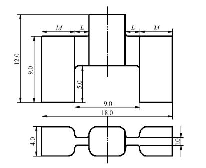
1 冲击剪切实验 1.1 试样设计本文所设计的新型双剪切试样具有1个加载端和2个支撑端,之间是两处相同的矩形剪切区域,几何外形呈"品"型,见图1。通过改变剪切区尺寸可以使材料内产生不同的应力应变状态和变形速度。配合霍普金森压杆设计了圆形接头以限制试样支撑端的横向位移,并使试样与压杆直接接触,确保实验信号的准确性。实验时,可以采用高速摄影装置对剪 切区的变形和失效过程进行直接拍摄。
|
图1 新型双剪切试样示意图 Fig.1 Schematic diagrams of the new double-shear specimen |
采用传统的分离式霍普金森压杆技术对紫铜等材料进行了冲击剪切测试.撞击杆和入射杆材料均为18Ni钢,透射杆材料采用7075铝合金,以提高透射脉冲信号幅值。
根据一维应力波理论,可以由压杆中的应变信号得到压杆和试样界面处的力和位移,分别为
$\left. {\matrix{
{{F_{{\rm{input}}}} = {A_{{\rm{bar}}}}{E_1}\left( {{\varepsilon _i}(t) + {\varepsilon _r}(t)} \right)} \hfill \cr
{{F_{{\rm{output}}}} = {A_{{\rm{bar}}}}{E_2}{\varepsilon _t}(t)} \hfill \cr
} } \right\}{\rm{ }}$
(1)
$\left. \matrix{
{U_{{\rm{input}}}} = {C_1}\int_0^t {\left( {{\varepsilon _i}(t) - {\varepsilon _r}(t)} \right)} dt \hfill \cr
{U_{{\rm{output}}}} = {C_2}\int_0^t {{\varepsilon _t}} (t)dt \hfill \cr} \right\}$
(2)
$\left. \matrix{
\tau (t) = {{({F_{{\rm{input}}}} + {F_{{\rm{output}}}})/2} \over {2{A_{\rm{s}}}}} \hfill \cr
\gamma (t) = {{{U_{{\rm{input}}}} - {U_{{\rm{output}}}}} \over L} \hfill \cr
\dot \gamma (t) = {{\gamma (t)} \over {{t_0}}} \hfill \cr} \right\}$
(3)
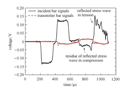
为便于对确定变形量下的材料进行回收分析,本文采用了单脉冲加载技术 [24],以避免应力波对试样重复加载。 图2给出了紫铜材料的典型测试信号,该实验中撞击杆长度为380 mm,试样剪切区宽度为2 mm。由图可知,入射杆内的反射波经加载端再次反射后,所形成的压缩信号幅值较低,基本转化为紧随其后的拉伸信号,说明单脉冲效果良好,避免了对试样的重复加载。由于试样本身的结构效应,使得入射波在加载端完全反射后试样与透射杆端部仍存在相互作用,因而透射信号脉宽较长,且下降沿较为平缓。
|
图2 典型实验波形图(L = 2 mm) Fig.2 Typical experimental signals(L = 2 mm) |
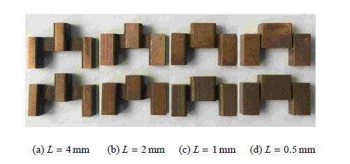
本文得到了紫铜在1 400 s- 1~75 000 s-1应变率范围的剪应力-剪应变曲线,见图3。由图知,材料的流动应力存在明显的应变率强化效应。当应变率超过45 000 s-1时,实验曲线的初始段出现较大振荡,但剪应力峰值及其后的塑性流动段仍随应变率的增加而进一步提高。在较低应变率下,流动应力随剪应变的增加而明显变大;当剪应变率升至45 000 s$^{-1}$时,加工硬化效应不明显,曲线基本在同一水平附近振荡;当应变率继续提高时,流动应力随着剪应变的增大呈现下降趋势。这说明随着应变率的提高,流动应力的加工硬化效应逐渐弱化。以上现象表明材料在剪切变形过程中存在应变率硬化、加工硬化和热软化相耦合的竞争机制。紫铜原始试样与回收试样的对比见图4。

|
图3 不同剪应变率下的剪应力--剪应变曲线 Fig.3 Shear stress--shear strain curves at different shear strain rates |
|
图4 原始试样(上) 和回收试样(下) 对比 Fig.4 Original (up) and recovered (down) specimens |
为验证实验方法的有效性,本文采用计算软件"ABAQUS/Explicit"对每组实验进行了数值模拟分析。 分别对压杆、试样及接头进行三维实体建模,并将入射应力脉冲作为初始条件均匀施加于入射杆的撞击端。由于压杆和接头不发生塑性变形,定义为弹性材料。压杆和接头采用"C3D8R"单元,试样采用"C3D10MT"温度位移耦合单元,以模拟剪切区内的温升。模型中紫铜热传导率为388 W/(m$ \cdot $K-1),比热为383 J/(kg$ \cdot $K-1),塑性功的产热系数为0。9。为准确模拟试样的剪切变形过程,试样材料采用实测的约翰逊-库克(Johnson-Cook)热黏塑性本构模型[25],以反映材料在变形过程的应变率和温度效应。
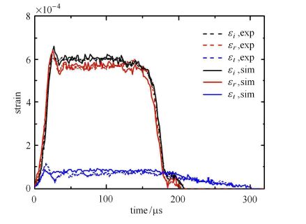
对图2所示的实验进行数值模拟,并将实验和模拟所得到的入射、反射和透射应变脉冲进行比较如图5所示。可以看出,入射、反射信号的模拟与实测结果基本重合,透射波的模拟曲线略高于实测值但与之非常接近,且两者趋势一致。总体而言,各实验信号与模拟结果均吻合较好,说明本文所采用的测试方法具有较高的准确性。
为考察试样两端的受力情况,分别输出入射杆/试样和透射杆/试样两界面处的载荷-时间曲线$F_{\rm input}$和$F_{\rm output}$,见图6。由图知,由于界面受到应力波传播与反射的影响,曲线存在较多振荡,但是两条曲线幅值基本一致,且变化趋势相同,说明试样两端在加载过程可以满足受力平衡条件。
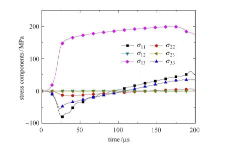
剪切区内各应力分量的平均值在加载过程的变化曲线见图7。 在整个加载过程中 $\sigma _{13}$均在很大程度上超过其他分量,说明剪切成分在该区域内占主导地位。对剪切区内的应力、应变分量进行考察可知,沿厚度方向不同路径上的各应力、应变分量值均保持稳定,观察不到明显的厚度效应;沿宽度和厚度方向,$\sigma_{13}$和$\varepsilon_{13}$幅值均显著高于其他分量,且材料较接近于纯剪切状态。由分析可知,处于剪切区中部大部分区域内的应力应变幅值分布较为平均,说明材料变形相对均匀,且该区域内剪切成分占主导地位。
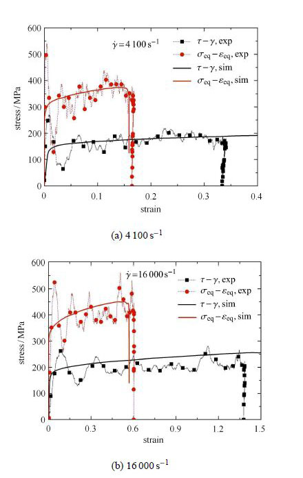
假设材料处于理想的纯剪切状态,根据实验结果可由式(4)得到材料的等效应力,并由大变形下剪应变与等效应变的关系式(5) [26]得到材料的等效应变 效应力-等效应变曲线分别与模拟结果的对比。 可以看出,在各应变率下实测的剪应力-剪应变曲线及转化得到的等效应力-等效应变曲线均与模拟结果吻合较好,说明本文所提出的实验方法可以方便、有效地测得材料在冲击载荷下的剪切性能,所得到的剪应力-剪应变曲线能准确反映材料的本构特性。
|
图5 入射、反射和透射应变信号的实验和模拟结果比较 Fig.5 Comparison between the experimental and the simulated results of the incident, reflected and transmitted strain waves |

|
图6 试样两端在加载过程中的载荷曲线比较 Fig.6 Comparison between the forces of the loading and supporting ends of the specimen |
|
图7 剪切区内各应力分量的变化情况 Fig.7 Comparison of different stress components in the shear zone |
|
图8 两种应变率下实验与模拟结果的比较 Fig.8 Comparison between experimental and simulation results of tests under two strain rates |
基于传统SHPB系统和新设计的 "品"型双剪切试样提出了一种用于材料高应变率剪切性能测试的新型加载技术。采用该方法可以在10$^{3}\sim $10$^{5 }$s$^{ - 1}$应变率范围内实现对材料冲击剪切性能的精确测量,同时可以采用高速摄影对材料的变形过程进行直接观测。结合单脉冲加载技术,可以避免应力波对试样的重复加载。 获得了紫铜在1 400$\sim $75 000 s$^{ - 1}$应变率范围的剪应力-剪应变曲线。通过数值模拟分析,发现剪切区主要区域内的应力应变场基本呈均匀分布,实测的剪应力-剪应变曲线与模拟结果吻合较好。本文所提出的测试方法可以在较高应变率下为材料动态剪切力学特性的研究提供方便有效的测试途径。
| [1] | Hopkinson B. A method of measuring the pressure produced in the detonation of high explosives or by the impact of bullets. Proceedings of the Royal Society of London A Mathematical Physical & Engineering Sciences, 1914, 213(89): 411-413 |
| [2] | Davies RM. A critical study of the hopkinson pressure bar. Philosophical Transactions of the Royal Society A Mathematical Physical & Engineering Sciences, 1948, 240(821): 375-457 |
| [3] | Kolsky H. An investigation of the mechanical properties of materials at very high rates of loading. Proceedings of the Physical Society,1949, 62(11): 676-700 |
| [4] | 段祝平, 孙琦清, 杨大光等. 高应变率下金属动力学性能的实验与理论研究- 一维杆的实验方法及其应用. 力学进展, 1980,10(1): 1-16 (Duan Zhuping, Sun Qiqing, Yang Daguang. Experimental and theoretical study on the dynamic properties of metal under high strain rate-Experimental method and application of dimension bar. Advances in Mechanics, 1980, 10(1): 1-16 (in Chinese)) |
| [5] | 李玉龙, 郭伟国,徐绯等. Hopkinson 压杆技术的推广应用. 爆炸与冲击, 2006, (26): 385-394 (Li Yulong, Guo Weiguo, Xü Fei. Popularization and application of Hopkinson pressure bar technique. Explosion and Shock Waves, 2006, (26): 385-394 (in Chinese)) |
| [6] | Murr LE, Staudhammer KP, Meyers MA. Metallurgical Applications of Shock Wave and High Strain Rate Phenomena. New York: Dekker Mechanical Engineering, 1986 |
| [7] | Meyer LW, Staskewitsch E, Burblies A. Adiabatic shear failure under biaxial dynamic compression/shear loading. Mechanics of Materials,1994, 17(2): 203-214 |
| [8] | Rittel D, Lee S, Ravichandran G. A shear-compression specimen for large strain testing. Experimental Mechanics, 2002, 42(1): 58-64 |
| [9] | Dorogoy A, Rittel D, Godinger A. A shear-tension specimen for large strain testing. Experimental Mechanics, DOI 10.1007/s11340-015-0106-1 |
| [10] | 林艺生, 傅学金, 杨月诚. 30CrMnSiA 绝热剪切带显微观察与分析. 兵器材料科学与工程, 2010, 33(6): 59-61 (Lin Yisheng, Fu Xuejin, Yang Yuecheng. Microscopic observation and analysis of adiabatic shear band 30CrMnSiA. Ordnance Material Science and Engineering, 2010, 33 (6): 59-61 (in Chinese)) |
| [11] | Meyers MA, Chen YJ, Marquis FDS, et al. High-strain, high-strainrate behavior of tantalum. Metallurgical & Materials Transactions A, 1995, 26(10): 2493-2501 |
| [12] | 魏志刚, 李永池. 冲击载荷作用下钨合金材料绝热剪切带形成机理. 金属学报, 2005, 36(12): 1263-1268 (Wei Zhigang, Li Yongchi. The formation mechanism of adiabatic shear band formation mechanism of tungsten alloy materials under impact loading. Journal of Metals, 2005, 36 (12): 1263-1268 (in Chinese)) |
| [13] | Hartmann KH, Kunze HD, Meyer LW. Shock Waves and Highstrain- rate Phenomena in Metals. Springer US, 1981 |
| [14] | Ferguson WG, Hauser FE, Dorn JE. Dislocation damping in zinc single crystals. British Journal of Applied Physics, 1967, 18: 411-417 |
| [15] | Dodd B, Bai Y. Adiabatic Shear Localization. Frontiers and Advances: Elsevier, London, 2012 |
| [16] | Campbell JD, Ferguson WG. The temperature and strain rate dependence of shear strength of mild steel. Philosophical Magazine,1970, 21(169): 63-82 |
| [17] | Ruiz DJ, Harding J, Ruiz C. High strain rate testing of materials - a fully validated test calibration by a hybrid numerical/experimental technique. Journal De Physique IV, 1991, C3: 465-470 |
| [18] | Klepaczko JR. An experimental technique for shear testing at high and very high strain rates. The case of a mild steel. International Journal of Impact Engineering, 1994, 15(1): 25-39 |
| [19] | Klepaczko JR. Remarks on impact shearing. Journal of the Mechanics & Physics of Solids, 1998, 46(10): 2139-2153 |
| [20] | Rusinek A, Klepaczko JR. Shear testing of a sheet steel at wide range of strain rates and a constitutive relation with strain-rate and temperature dependence of the flow stress. International Journal of Plasticity,2001, 17(1): 87-115 |
| [21] | Guo Y, Li Y. A novel approach to testing the dynamic shear response of Ti-6Al-4V. Acta Mechanica Solida Sinica, 2012, 25(3): 299-311 |
| [22] | Shi FF, Merle R, Hou B, et al. A critical analysis of plane shear tests under quasi-static and impact loading. International Journal of Impact Engineering, 2014, 74: 107-119 |
| [23] | Clifton RJ, Klopp RW. Pressure-shear plate impact testing. Metals Handbook, 1985, 8(9): 230 |
| [24] | Nemat-Nasser S. Hopkinson techniques for dynamic recovery experiments. Proceedings of the Royal Society A Mathematical Physical & Engineering Sciences, 1991, 435(1894): 371-391 |
| [25] | Xu ZJ, Huang FL. Comparison of constitutive models for FCC metals over wide temperature and strain rate ranges with application to pure copper. International Journal of Impact Engineering, 2015, 79:65-74 |
| [26] | Culver RS. Thermal Instability Strain in Dynamic Plastic Deformation. In: Rohde RW, eds. Metallurgical Effects at High Strain Rates, New York, NY: Plenum Press, 1973. 519-530. |
 2016, Vol. 48