电子产品的小型化和集成电路的大规模化是目前电子设备的发展趋势,随着电子设备中电子元器件的功率不断增大和物理尺寸逐渐减小,其内部产生的热量如何高效的疏导到冷却区域是首要解决的关键问题.电子产品的温度控制直接影响设备的工作性能和效率,且随着温度的升高,电子器件的失效率呈指数增长趋势.基于此,研究者提出了许多方法来实现电子设备的冷却,如翅片散热[1, 2],微流道[3, 4, 5, 6],植入式导热通道[7, 8, 9, 10, 11, 12]等.其中,植入式导热通道(如电子设备热源内部植入高导热材料形成高效散热通道的方式)在近期尤为受到关注[13, 14, 15].这种散热方式相比于翅片和微流道大大节省了空间,有利于电子设备的小型化,并且三维打印技术(增材制造)的快速发展为含有植入式导热材料的电子器件的制备提供了技术支撑[16].因此,针对植入式导热通道,如何设计高导热材料的布局,实现热源内部热量的高效收集和传输是需要研究的重要问题.
许多研究工作者已经开展了一些散热通道优化设计的工作,建立了计算模型和相应的求解方法.例如,有学者基于构形理论建立了体-点(volume-to-point)散热问题的设计方法[7],构形理论从一个最优的基本元件出发,通过不同层级和尺度的最优元件的组装,获得高导热材料的最优布局,实现结构最高温度的最小化.过增元等[17]以最小热势容耗散为目标,建立了导热结构的设计理论和方法. 程新广等[18]基于生物进化准则实现多种工况下的高导热材料的布局设计.还有学者通过经验和直觉提出了多种形式的传热路径设计方案[13, 14],如$\Phi $型,$\Psi $型,X型等,并对其进行了尺寸和形状的优化设计,取得了较好的效果.
结构拓扑优化通过设计材料在空间的合理分布,能够获得创新结构形式[19, 20, 21, 22, 23, 24].在热传导结构拓扑优化方面,已经开展了一些相关的研究工作.例如,李青等[25]采用双向进化算法(BESO)拓扑优化方法实现了热传导结构的拓扑优化设计,汉森等[26]将有限体积法运用到稳态热传导问题中,以散热弱度为目标,获得了最优的散热结构形式.刘书田和张永存[27]研究了体-点问题的导热通道优化设计问题,并与仿生优化的结果进行了比较,发现通过拓扑优化设计能够获得更为有效的散热路径. 此外,张晖等[28]研究了热载荷相关性问题.以上工作表明,拓扑优化已经成为导热路径设计的有效方法.但之前的设计中,优化模型均是在给定热源条件下优化高导热材料的布局,没有考虑导热通道的布局对热源布局的影响.这些设计方法可用于贴片式(高导热材料附着在被冷却体上)散热结构的设计.
对于植入式导热通道设计问题,结构由自发热材料和高导热材料构成. 植入的高导热材料仅起输送热量的作用而不产热,它的布置对热源(即芯片材料)的分布必将产生影响,同时热源的分布反过来影响高导热材料的最优布局. 因此,优化模型应包含导热通道的布局对热源布局的影响,而之前的散热结构拓扑优化模型没有考虑热源与导热通道布局的相互影响. 需要建立包含热源布局与导热通道布置相关的最优散热通道设计方法.
针对上述研究背景,本文基于拓扑优化建立植入式导热路径的设计方法,协同设计高导热材料和热源材料布局优化问题. 基于单元密度拓扑描述方法,以高导热材料的相对密度为导热路径的描述参数,分别选择合适插值模型,建立热传导系数和生热率与高导热材料相对密度的关系,并以结构散热弱度最小为目标,建立植入式导热结构最优布局设计的拓扑优化模型和求解方法. 通过数值算例验证本文所提出方法的正确性和有效性,同时验证考虑植入高导热材料对热源布局影响的必要性.
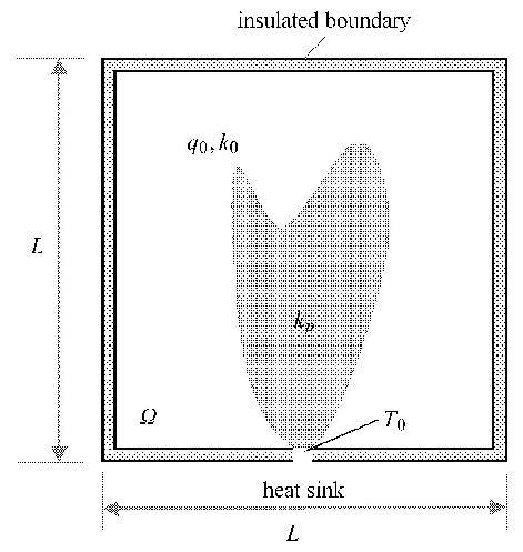
1 设计问题的建立和求解 1.1 导热路径的拓扑描述考虑图1所示稳态热传导问题,方形设计域 $\Omega $ 内含自发热材料(比如,芯片材料等),该自发热材料具有较低的热传导率 $k_0 $ 以及单位面积生热率 $q_0 $,方形域 $\Omega $ 所有的边界为绝热边界除了下底边中点处的热沉. 通过在域内植入一定体积的高导热材料(热传导系数$k_p $),并设计高导热材料的布局,使热量快速传递到边界热沉处耗散.
|
图1 体-点问题 Fig.1 Volume-to-point problem |
通常情况下,对于导热路径的拓扑优化设计,目前大部分的研究工作仅考虑高导热材料的布局问题[19, 20],自发热材料的布局并不受高导热材料布局的影响,即在计算过程中热源是确定的(算例1中将进一步说明).采用基于固体各向同性材料惩罚模型(SIMP)的密度描述,将设计域离散为$N$个有限单元,第$j$个单元内高导热材料的含量用单元密度(设计变量) $\rho _j $ 来表征. 单元密度值 $\rho _j = 1$,表示单元填充高导热材料,其热传导系数为$k_p $;而当 $\rho _j = 0$,该单元填充自发热材料,其热传导系数为$k_0 $.根据单元密度描述方法的思想,在优化过程中,相对密度取值连续化,即$\rho _j \in \left[{0, 1} \right]$,第$j$个单元的热传导系数与相对密度值取以下插值形式 $$ k_j = k_0 + \rho _j^{P_1 } (k_p - k_0 ) \tag{1}$$ 其中,$P_1 $为惩罚系数.
对于植入式导热路径设计问题,高导热材料本身并不产热,它的植入对热源材料的分布产生影响,同时热源材料的分布反过来影响高导热材料的最优布局. 为了在设计过程中描述上述情况,以高导热材料的相对密度作为热源分布的描述参数.区域内某子域(单元)的相对密度为1,表示该子区域内无热源(发热率为0),而相对密度为0,则表示该区域存在热源,其发热率为给定的自发热材料的发热率$q_0 $.仿照热传导系数的材料插值模型,在优化迭代过程中,发热率与相对密度的关系取以下形式的插值模型: $$ q_j = q_0 (1 - \rho _j^{P_2 } ) \tag{2}$$ 本文计算中,选取$P_1 = 3$, $P_2 = 1$.
1.2 设计问题的建立对于稳态热传导问题,有限元控制方程可以为 $$ { K T} ={ P} \tag{3}$$ 其中,${ K} $为总热传导矩阵,${ T} $为节点温度向量,$ { P}$为热载荷向量. 本文中采用最小散热弱度(热势容)$C = { P}^{\rm T}{ T}$ 作为设计目标,建立如下拓扑优化问题的提法 $$ \left. {\begin{array}{*{20}{c}} {X = {{\left( {{\rho _1},{\rho _2}, \cdots ,{\rho _j}, \cdots {\rho _N}} \right)}^{\rm{T}}}}\\ {{\rm{min}}:C = {P^{\rm{T}}}T}\\ {{\rm{s}}.{\rm{t}}.:\sum\limits_{j = 1}^N {{v_j}} {\rho _j}/V = {v_{\rm{f}}}} \end{array}} \right\}\tag{4}$$ 式中,$v_j $为第 $j $个单元的面积(体积),$V$为设计域$\Omega $ 的面积(体积),$v_{\rm f} $为体积分数.
1.3 敏度分析目标函数关于设计变量的敏度可以表达为 $$ \dfrac{\partial C}{\partial \rho _j } = \left( {\dfrac{\partial { P }}{\partial \rho _j }} \right)^{\rm T}{ T } + { P }^{\rm T}\dfrac{\partial { T }}{\partial \rho _j } \tag{5}$$ 对平衡方程(3)取微分可以得到 $$ \dfrac{\partial { K }}{\partial \rho _j }{ T} + { K }\dfrac{\partial { T} }{\partial \rho _j } = \dfrac{\partial { P} }{\partial \rho _j } \tag{6}$$ 于是${\partial { T}} /{\partial \rho _j }$ 可以写成 $$ \dfrac{\partial { T} }{\partial \rho _j }={ K }^{ - 1}\dfrac{\partial { P} }{\partial \rho _j } - { K }^{ - 1}\dfrac{\partial { K} }{\partial \rho _j }{ T } \tag{7}$$ 将式(7)代入式(5),可以得到目标函数的敏度可以表达为 $$ \dfrac{\partial C}{\partial \rho _j } = 2\left( {\dfrac{\partial { P} }{\partial \rho _j }} \right)^{\rm T}{ T} - { T }^{\rm T}\dfrac{\partial { K} }{\partial \rho _j }{ T}=\\ 2\left( {\dfrac{\partial { P }_j }{\partial \rho _j }} \right)^{\rm T}{ T }_j - { T }_j^{\rm T} \dfrac{\partial { K }_j }{\partial \rho _j }{ T }_j \tag{8}$$ 其中,${ P }_j $为第$j$个单元的节点热载荷向量,可以通过如下列式求得 $$ { P }_j = \int_{\Omega _e } q_j { N }_j d \Omega _e \tag{9}$$ 其中,${ N}_j $为单元形函数矩阵. 因此,将材料差值模型式(1)和式(2)代入式(8),就可以获得目标函数敏度的解析表达 $$ \dfrac{\partial C}{\partial \rho _j } = - 2P_2 \rho _j^{P_2 - 1} \left( {\int_{\Omega _e } q_0 { N }_j d\Omega _e } \right) { T}_j -\\ P_1 \rho _j^{P_1 - 1} (k_p - k_0 ){ T }_j^{\rm T } { K }_e^0 { T }_j \tag{10}$$ 若计算过程中认为高导热材料的布置不影响热源的布局,此时,目标函数的敏度可以表达为 $$ \dfrac{\partial C}{\partial \rho _j } = - P_1 \rho _j^{P_1 - 1} (k_p - k_0 ){ T }_j^{\rm T } { K }_e^0 { T }_j \tag{11}$$ 其中,$K_e^0 $ 为具有单位热传导系数的单元热传导矩阵. 对于二维正方形单元,${ K}_e^0 $可以写成 $$ { K}_e^0 = \left[\!\!\begin{array}{cccc} {\dfrac{2}{3}} & { - \dfrac{1}{6}} & { - \dfrac{1}{3}} & { - \dfrac{1}{6}} \\ { - \dfrac{1}{6}} & {\dfrac{2}{3}} & { - \dfrac{1}{6}} & { - \dfrac{1}{3}} \\ { - \dfrac{1}{3}} & { - \dfrac{1}{6}} & {\dfrac{2}{3}} & { - \dfrac{1}{6}} \\ { - \dfrac{1}{6}} & { - \dfrac{1}{3}} & { - \dfrac{1}{6}} & {\dfrac{2}{3}} \end{array}\!\!\right] \tag{12}$$ 从式(10)和式(11)可以看出,对于是否考虑高导热材料的布置对于热源的影响,目标函数敏度的表达具有非常大的差别.
为了避免棋盘格现象和尽可能减少网格相关性,在本文计算中采用了敏度过滤技术,改写敏度形式如下 $$ \left. \begin{align} & \frac{\partial \tilde{C}}{\partial {{\rho }_{j}}}=\sum\limits_{i=1}^{n}{{{{\hat{H}}}_{i}}}{{\rho }_{i}}\frac{\partial C}{\partial {{\rho }_{i}}}/{{\rho }_{j}}\sum\limits_{i=1}^{n}{{{{\hat{H}}}_{i}}} \\ & {{{\hat{H}}}_{i}}={{r}_{\min }}-\text{dist}(j,i),\{i\in n|\text{dist}(j,i)\le {{r}_{\min }}\} \\ \end{align} \right\} \tag{13}$$ 其中,${\rm dist}(j, i)$为单元$j$与单元$i$中心之间的距离,$r_{\min } $为过滤半径.
1.4 迭代流程本文中,优化列式(4)的求解采用序列线性规划方法(SLP). 完整的拓扑优化迭代流程如下:
步骤1:问题初始化. 定义设计域、设计变量初值和过滤半径,施加载荷和边界条件.
步骤2:稳态温度场分析. 将设计与离散成有限元网格,采用有限元法计算式(3),获得结构温度场.
步骤3:目标函数与敏度计算. 计算目标函数,以及通过式(10)获得目标函数关于设计变量的敏度表达,并通过式(13)对敏度进行过滤.
步骤4:设计变量更新. 采用序列线性规划方法(SLP)对设计变量进行更新.
步骤5:收敛判断. 若收敛,迭代停止;若不收敛,返回步骤2,重复步骤2$\sim$5.
2 算例与讨论本节采用二维拓扑优化算例验证所提出的方法的正确性和有效性. 为了对比不同的计算结果,定义无量纲峰值温度[27, 29]为 $$ \tau = \dfrac{T_{\max } - T_{\min } }{{q_0 A}/{k_0 }} \tag{14}$$ 其中,$T_{\max } $和$T_{\min } $分别为设计域 $\Omega $ 中的最大温度和最小温度. $\tau $值越小表明结构的导热性能越好.
算例中结构尺寸和材料单位均采用无量纲量. 如图1所示,结构尺度为100 ×100,采用正方形平面单元离散结构,单元边长为1. 发热材料的热传导系数为$k_0 = 0.01$,高导热材料热传导系数为$k_p = 1$,设计域内发热材料单位面积生热率均为$q_0 = 0.01$,热沉处温度为$T_0 = 0$,体积分数 $v_{\rm f} = 0.15$. 优化参数过滤半径 $r_{\min } = 2$,初始材料布局均为材料相对密度(设计变量)为体积分数的均匀分布.
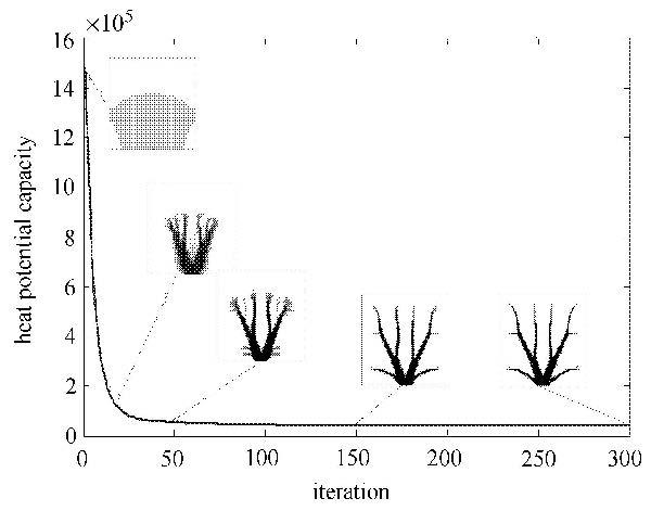
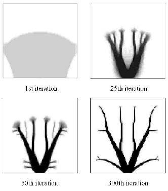
2.1 算例1:贴片式散热通道设计本算例在计算过程中认为热源是均匀分布的,忽略高导热材料的布置对于热源的影响,仅采用式(1)的材料差值格式,通过式(11)的敏度分析更新设计. 图2给出了目标函数的迭代历史以及高导热材料布局的演化情况,图3给出了第1, 25, 50, 300迭代步拓扑结果,图中设计域内黑色部分表征高导热材料,白色区域为自发热材料. 从高导热材料布局演化过程可以看出,从靠近热沉处开始布置,随后延伸进入远离热源的区域,最终汇聚到热沉处耗散.
|
图2 目标迭代历史 Fig.2 Iteration history of objective function |
|
图3 第1, 25, 50, 300迭代步拓扑结果 Fig.3 Topology results of 1st, 25th, 50th, 300th iterations |
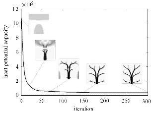
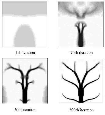
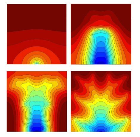
本算例中考虑植入高导热材料对热源布局影响,采用式(1)和式(2)材料差值模型,通过式(10)的敏度分析更新设计.图4给出了目标函数的迭代历史以及高导热材料布局的演化情况.从图4中可以看出,目标函数值随着迭代数的增加平稳下降,最终收敛,最优拓扑为类似树形的结构.高导热材料布局演化过程与算例1具有明显不同,高导热材料的布置同时受到热沉(散热处)和热流载荷的影响,迭代开始时将材料布置在靠近热沉处和远离热沉处(温度较高),这种布局方式能够将靠近热沉的热量迅速传走,并且使得远离热沉处(高温区域)的发热量减少.随后两部分材料逐渐相连形成散热通道,将远离热沉区域的热量传递出来,最终获得最优结果.为了进一步说明上述现象,图5给出了第1, 25, 50, 300迭代步拓扑结果,图6给出了相应的温度场分布.
|
图4 目标迭代历史 Fig.4 Iteration history of objective function |
|
图5 第1, 25, 50, 300迭代步拓扑结果 Fig.5 Topology results of 1st, 25th, 50th, 300th iterations |
|
图6 第1, 25, 50, 300迭代步温度场 Fig.6 Temperature field results of 1st , 25th , 50th , 300th iterations |
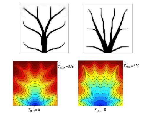
图7给出了算例1和算例2的结果对比,可以发现忽略植入高导热材料对热源布局影响,无量纲峰值温度 $\tau = 0.062 0$,而考虑植入高导热材料对热源布局影响,无量纲峰值温度为 $\tau = 0.055 6$,相对性能提升了10.3%.
|
图7 结果对比 Fig.7 Comparison of results |
若采用构形理论设计本算例中的体-点问题,其极限的无量纲峰值温度[30]为 $$ \tau _{\rm limit} ={k_0 }/ (k_p v_{\rm f} ) = 0.066 7 \tag{15}$$ 该结果要明显大于采用拓扑优化获得的结果.
3 结论本文建立了实现自发热体最优冷却的植入式导热路径设计的拓扑优化模型和求解方法. 通过引入合适的插值模型、高导热材料的相对密度,以实现导热路径(高导热材料的布局)的描述以及受导热路径影响的热源分布的描述. 算例的设计结果验证了本文方法对植入式导热通道设计的有效性. 植入式散热路径与贴片式散热路径设计结果的比较表明,两种最优散热构型存在很大不同,说明对于植入式散热结构设计,优化模型中考虑高导热材料对热源分布的影响非常必要. 此外,高导热材料与发热材料的导热系数之比以及高导热材料的用量对最优导热路径的构型均有影响,对于这些影响的讨论将是在后续研究应关注的问题.
| 1 | Ndao S, Peles Y, Jensen MK. Effects of pin fin shape and configuration on the single-phase heat transfer characteristics of jet impingement on micro pin fins. International Journal of Heat and Mass Transfer, 2014, 70:856-863 |
| 2 | Patel V, Savsani V. Optimization of a plate-fin heat exchanger design through an improved multi-objective teaching-learning based optimization(MO-ITLBO) algorithm. Chemical Engineering Research and Design, 2014, 92(11):2371-2382 |
| 3 | Xie G, Zhang F, Sundén B, et al. Constructal design and thermal analysis of microchannel heat sinks with multistage bifurcations in single-phase liquid flow. Applied Thermal Engineering, 2014, 62(2):791-802 |
| 4 | Zhang LY, Zhang YF, Chen JQ, et al. Fluid flow and heat transfer characteristics of liquid cooling microchannels in LTCC multilayered packaging substrate. International Journal of Heat and Mass Transfer, 2015, 84:339-345. |
| 5 | Mala GM, Li D, Dale J. Heat transfer and fluid flow in microchannels. International Journal of Heat and Mass Transfer, 1997, 40(13):3079-3088 |
| 6 | Lee S, Garimella SV, Liu D. Investigation of heat transfer in rectangular microchannels. International Journal of Heat and Mass Transfer, 2005, 48(9):1688-1704 |
| 7 | Bejan A. Constructal-theory network of conducting paths for cooling a heat generating volume. International Journal of Heat and Mass Transfer, 1997, 40(4):799-816 |
| 8 | Rocha L, Lorente S, Bejan A. Constructal design for cooling a discshaped area by conduction. International Journal of Heat and Mass Transfer, 2002, 45(8):1643-1652. |
| 9 | Chen L, Wei S, Sun F. Constructal entransy dissipation rate minimization of a disc. International Journal of Heat and Mass Transfer, 2011, 54(1):210-216 |
| 10 | Hajmohammadi M, Moulod M, Shariatzadeh OJ,et al. Essential reformulations for optimization of highly conductive inserts embedded into a rectangular chip exposed to a uniform heat flux. Proceedings of the Institution of Mechanical Engineers, Part C:Journal of Mechanical Engineering Science, 2014, 228(13):2337-2346 |
| 11 | Bejan A, Lorente S. The constructal law and the evolution of design in nature. Physics of Life Reviews, 2011, 8(3):209-240 |
| 12 | Feng H, Chen L, Sun F. Volume-point heat conduction constructal optimization based on entransy dissipation rate minimization with three-dimensional cylindrical element and rectangular and triangular elements on microscale and nanoscale. Science China Technological Sciences, 2012, 55(3):779-794 |
| 13 | Lorenzini G, Biserni C, Rocha LAO. Constructal design of X-shaped conductive pathways for cooling a heat-generating body. International Journal of Heat and Mass Transfer, 2013, 58(1):513-520 |
| 14 | Hajmohammadi M, Moulod M, Shariatzadeh OJ, et al. Phi and Psi shaped conductive routes for improved cooling in a heat generating piece. International Journal of Thermal Sciences, 2014, 77:66-74 |
| 15 | Chen L, Feng H, Xie Z, et al. Volume-point mass transfer constructal optimization based on flow resistance minimization with cylindrical element. International Journal of Heat and Mass Transfer, 2015, 89:1135-1140. |
| 16 | Gibson I, Rosen DW, Stucker B. Additive Manufacturing Technologies. Springer, 2010 |
| 17 | Guo Z, Cheng X, Xia Z. Least dissipation principle of heat transport potential capacity and its application in heat conduction optimization. Chinese Science Bulletin, 2003, 48(4):406-410 |
| 18 | Cheng X, Li Z, Guo Z. Constructs of highly effective heat transport paths by bionic optimization. Science in China Series E:Technological Sciences, 2003, 46(3):296-302 |
| 19 | Bendsøe M, Sigmund O. Material interpolation schemes in topology optimization. Archive of Applied Mechanics, 1999, 69(9-10):635-654 |
| 20 | 高兴军,马海涛. 连续体结构动力拓扑优化中局部模态处理的新方法. 力学学报, 2014, 46(5):739-746(Gao Xingjun, Ma Haitao. A new method for dealing with pseudo modes in topology optimization of continua for free vibration. Chinese Journal of Theoretical and Applied Mechanic, 2014, 46(5):739-746(in Chinese)) |
| 21 | 苏文政, 张永存, 刘书田. 考虑位移补偿的结构几何稳定性拓扑优化. 力学学报, 2013, 45(2):214-222(Su Wenzheng, Zhang Yongcun, Liu Shutian. Topology optimization for geometric stability of structures with compensation displacements. Chinese Journal of Theoretical and Applied Mechanic, 2013, 45(2):214-222(in Chinese)) |
| 22 | 高彤, 张卫红. 多相材料结构拓扑优化:体积约束还是质量约束? 力学学报, 2011, 43(2):296-305(Gao Tong, Zhang Weihong. Topology optimization of structures designed with multiphase materials:volume constraint or mass constraint? Chinese Journal of Theoretical and Applied Mechanic, 2011, 43(2):296-305(in Chinese)) |
| 23 | 杜建镔, 宋先凯, 董立立. 基于拓扑优化的声学结构材料分布设计. 力学学报, 2011, 43(2):306-315(Du Jianbin, Song Xiankai, Dong Lili. Design of material distribution of acoustic structure using topology optimization. Chinese Journal of Theoretical and Applied Mechanic, 2011, 43(2):306-315(in Chinese)) |
| 24 | 刘虎, 张卫红, 朱继宏. 简谐力激励下结构拓扑优化与频率影响分析. 力学学报, 2013, 45(4):588-597(Liu Hu, Zhang Weihong, Zhu Jihong, Structural topology optimization and frequency influence analysis under harmonic force excitations. Chinese Journal of Theoretical and Applied Mechanic, 2013, 45(4):588-597(in Chinese)) |
| 25 | Li Q, Grant PS, Xie YM, et al. Evolutionary topology optimization for temperature reduction of heat conducting fields. International Journal of Heat and Mass Transfer, 2004, 47(23):5071-5083 |
| 26 | Hansen A, Bendsøe M, Sigmund O. Topology optimization of heat conduction problems using the finite volume method. Structural and Multidisciplinary Optimization, 2006, 31(4):251-259 |
| 27 | Zhang Y, Liu S, Design of conducting paths based on topology optimization. Heat and Mass Transfer, 2008, 44(10):1217-1227 |
| 28 | 张晖, 刘书田, 张雄. 拓扑相关热载荷作用下稳态热传导结构拓扑优化. 中国机械工程, 2009, 11:1339-1343(Zhang Hui, Liu Shutian, Zhang Xiong. Topology optimization of steady-state heat conduction problem with design-dependent heat loads. China Mechanical Engineering, 2009, 11:1339-1343(in Chinese)) |
| 29 | Xie Z, Chen L, Sun F. Constructal optimization on T-shaped cavity based on entransy dissipation minimization. Chinese Science Bulletin, 2009, 54(23):4418-4427 |
| 30 | WuW, Chen L, Sun F. Improvement of tree-like network constructal method for heat conduction optimization. Science in China Series E, 2006, 49(3):332-341 |
 2016, Vol. 48