研究高温真实气体效应时,需要在地面实验设备中能够实现高焓气体流动. 当前国际上实现高焓气体流动的实验手段之一是自由活塞驱动类脉冲设备,包括自由活塞激波风洞和自由活塞膨胀管. 前者包括HEG [1, 2]、T5 [3, 4]和HIEST [5, 6]等,后者包括X2 [7]、X3 [8, 9]和JX-1 [10, 11]等. 自由活塞压缩管的驱动能力在很大程度上决定了自由活塞驱动类设备的试验性能.
自20世纪60年代起,国外学者Stalker [12, 13]、Hornung [14]、Itoh [15, 16]等先后对压缩管内部的自由活塞运动理论进行了研究. Jacobs[17, 18, 19]采用拉格朗日方法数值模拟了自由活塞激波风洞的性能,获得了自由活塞运动特征.Mitsuda等[20]则基于欧拉方法[21]模拟了自由活塞驱动类设备性能. Bensassi等[22]采用任意拉格朗日欧拉方法(arbitrary Lagrangian Eulerian,ALE方法)模拟了高超声速实验设备中的活塞运动,但是未和相关数据进行对比.在ALE方法[23, 24, 25]中,计算网格可像普通拉格朗日方法一样允许其和流体以相同速度运动,也可像欧拉方法一样静止固定.当计算网格在边界处与边界一起运动时,可以保证边界的高分辨率和捕捉能力,而远离界面处的网格运动可以做到网格自适应,对数值解的某些特征可以实现高质量的模拟.
为分析自由活塞压缩管驱动性能和模拟今后的自由活塞激波风洞与膨胀管性能,本文引入ALE方法,数值求解压缩管内气体非定常准一维流动和活塞运动. 为提高时间精度,采用了双时间步长积分方法[26, 27, 28].移动网格控制体面积矢量和网格速度计算满足几何守恒律(geometric conservation law)[29, 30, 31].通过与简单波理论模型及自由活塞运动欧拉方法数值结果对比,来分析方法的可靠性.
1 计算方法控制方程组为ALE形式的守恒型Euler方程[22, 32].采用双时间步长方法进行积分时,为满足几何守恒律[29, 31],运动网格控制体法向矢量和表面面积采用如下方法[31] 计算 $$ { s}_E \cdot { v}_{G,E} = \dfrac{1}{\Delta t}\left( {\dfrac{3}{2}\Delta \Omega _{c,E}^n - \dfrac{1}{2}\Delta \Omega _{c,E}^{n - 1} } \right) \tag{1}$$ 式中,${ s}_E $和${ v}_{G,E}$ 分别为控制体表面$E$的面积矢量和速度矢量,$\Delta \Omega _{c,E}^n $和$\Delta \Omega _{c,E}^{n - 1}$ 分别为表面 $E$在$n$和$n-1$时间层扫过的体积.不考虑气体泄漏及活塞摩擦时,活塞运动方程为 $$ W_{\rm p} \dfrac{d V_{\rm p} }{d t} = A\left( {p_{\rm b} - p_{\rm f} } \right) \tag{2}$$ 其中,$W_{\rm p} $和$V_{\rm p} $分别是活塞质量和速度,$p_{\rm b} $和$p_{\rm f} $分别是活塞后表面和前表面的压力.气体泄露因素对活塞运动影响可以忽略[14, 15],摩擦效应对活塞运动的影响可以通过在活塞前表面压力项中添加基于实际工程经验和理论分析而确定的因子来考虑[15].
2 计算结果与简单波理论模型的对比学者Hornung[14]为分析压缩管性能和活塞运动特征,提出了一种活塞运动简单波理论模型.模型假设活塞后部空气压缩管无限长,即从活塞出发的稀疏波没有发生再次反射回活塞后表面的情况.
这里给出两组参数,第1组参数(Case1):空气罐容积50 m$^{3}$;压缩管长度26 m;内径0.6 m;活塞重量500 kg;初始空气压力180 atm;驱动气体摩尔比例$x_{N_2 } : x_{H_2 } = 3:17$;初始压力121 kPa;破膜压力20.2 MPa.第2组参数(Case2)除空气罐容积不一样之外(1 m$^{3}$),其他参数与第1组参数相同.
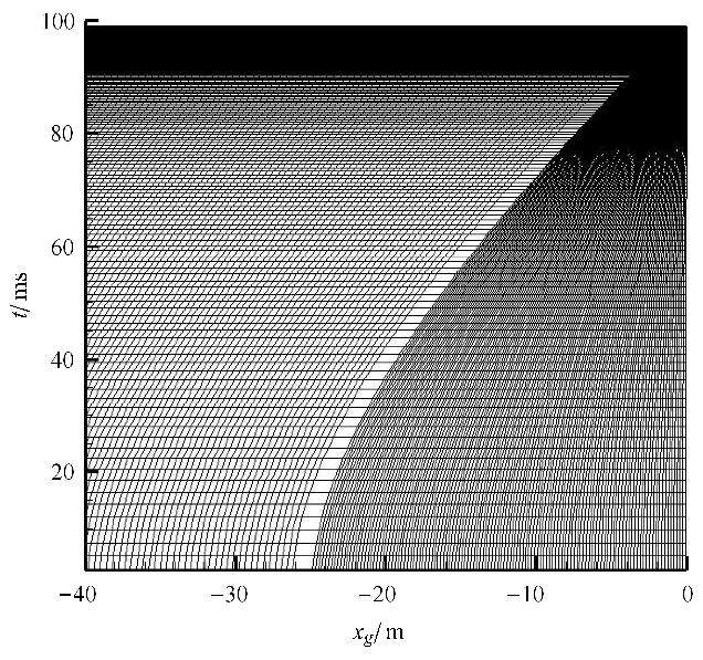
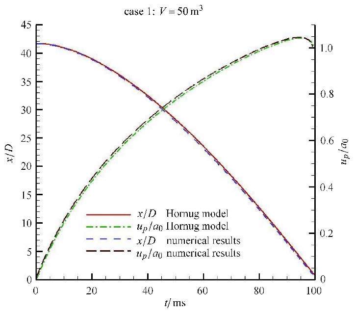
图1给出了运动网格坐标随时间变化示意图. 活塞两侧附近网格位置与活塞位置变化趋势一致,而靠近压缩管右端膜片的网格接近静止. 图2和图3显示了数值和简单波理论模型结果.关于活塞速度、活塞到膜片距离以及活塞前后表面压力分别采用初始空气声速$a_0 $、压缩管内径$D$和初始空气压力$p_0 $进行了无量纲化,二者很吻合. 活塞头部表面压力的数值结果出现了一系列折线,这是驱动气体压缩波在活塞头部和压缩管末端膜片间来回反射的结果(图4).

|
图1 不同时刻的计算网格 Fig.1 Computational grids at different times |

|
图2 第1组参数条件下破膜前不同时刻活塞速度和到膜片距离 Fig.2 Piston velocity and the distance from the diaphragm at different times before diaphragm rupture for Case 1 |

|
图3 第1组参数条件下破膜前不同时刻活塞前后压力 Fig.3 Pressure at the front and back faces of the piston at different times before diaphragm rupture for Case 1 |

|
图4 第1组参数条件下压力自然对数位置时间图 Fig.4 X-time diagram of pressure field in logarithmic for Case 1 |
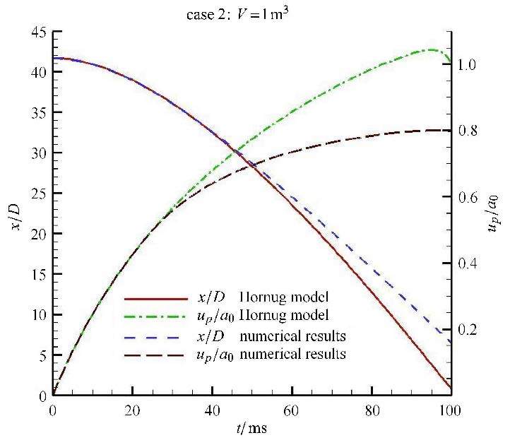
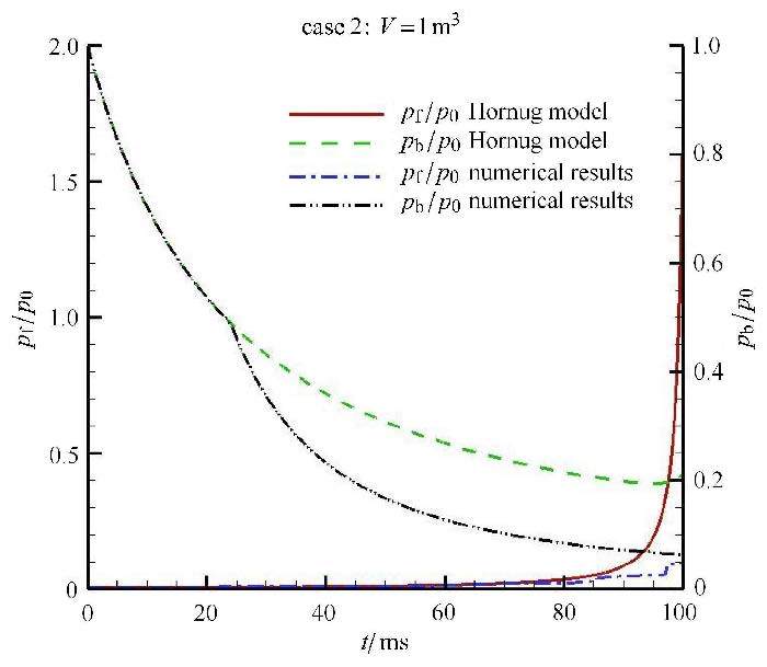
第2组参数情况下,从图5和图6中的比较来看,数值结果和简单波理论模型差别较大.由于空气罐容积很小,很难满足活塞后部空气压缩管无限长的假设,由活塞后表面发出的稀疏波出现了到达压缩管左端壁面后再次反射到活塞底部的现象 (图7),导致压力降低(图6),因此简单波理论模型和数值结果差别较大.

|
图5 第2组参数条件下破膜前不同时刻活塞速度和到膜片距离 Fig.5 Piston velocity and the distance from the diaphragm at different times before diaphragm rupture for Case 2 |

|
图6 第2组参数条件下破膜前不同时刻的活塞前后压力 Fig.6 Pressure at the front and back faces of the piston at different times before diaphragm rupture for Case 2 |

|
图7 第2组参数条件下压力自然对数位置时间图 Fig.7 X-time diagram of pressure field in logarithmic for Case 2 |
这里同国外欧拉方法数值结果及实验测量数据[20]进行对比.分别针对压缩管末端出现直接撞击的重活塞(2.0 kg)和出现反弹的轻活塞(0.4 kg)两种情况[20]进行计算.图8显示了两种活塞的运动轨迹. 可以看到:采用ALE方法获得的结果与文献计算和测量结果比较吻合.

|
图8 破膜前压缩管内2.0/0.4 kg活塞轨迹 Fig.8 The piston trajectory in the compression tube for 2.0/0.4 kg pistons before diaphragm rupture |
自由活塞压缩管作为自由活塞驱动类的激波风洞和高焓膨胀管驱动段,其驱动能力在很大程度上要影响该类试验设备的性能. 采用ALE (arbitrary Lagrangian Eulerian)数值模拟自由活塞压缩管内的活塞运动和气体流动特征时,耦合求解网格运动和气体流动过程. 为了提高时间计算精度,采用双时间步长方法进行时间积分. 通过和目前存在的简单波理论模型和欧拉数值方法比较验证了这里建立的方法. 该工作为下一步采用ALE方法数值模拟自由活塞激波风洞和自由活塞膨胀管中包括压缩管、激波管和喷管等不同部位的耦合流动提供了基础.
| 1 | Hornung HG, Belanger J. Role and technique of ground testing for simulation of flows up to orbital speed. AIAA paper 90-1377, 1990 |
| 2 | Hannemann K, Schnieder M, Reimann B, et al. The influence and the delay of driver gas contamination in HEG. AIAA paper 2000-2593, 2000 |
| 3 | Hornung HG. Performance data of the new free piston shock tuunel at GALCIT. AIAA paper 92-3943, 1992 |
| 4 | Olejniczak J, Wright MJ, Laurence S, et al. Computational modeling of T5 laminar and turbulent heating data on blunt cones. part I:Titan applications. AIAA paper 2005-0176, 2005 |
| 5 | Itoh K, Komuro T, Sato K, Tanno H, et al. Hypersonic aerodynamic research of HOPE using high enthalpy shock tunnel. AIAA paper 2001-1824, 2001 |
| 6 | Tanno H, Komuro T, Sato K, et al. Free-flight tests of reentry capsule models in free-piston shock tunnel. AIAA paper 2013-2979, 2013 |
| 7 | Scott MP, Morgan RG, Jacobs A. A new single stage driver for the X2 expansion tube. AIAA paper 2005-697, 2005 |
| 8 | Silvester TB, Morgan RG, Jacobs PA. Skin friction measurements in a duct in the X3 superorbital expansion tube. AIAA paper 2004-3551, 2004 |
| 9 | Jacobs PA, Silvester TB, Morgan RG, et al. Superorbital expansion tube operation:estimates of flow conditions via numerical simulation. AIAA paper 2005-694, 2005 |
| 10 | Sasoh A, Ohnishi Y, Ramjaun D, et al. Effective test time evaluation in high-enthalpy expansion tube. AIAA Journal, 2001, 39(11):2141-2147 |
| 11 | Nagata T, Ohnishi N, Sasoh A, et al. Calculation of unsteady flowfield in expansion tube using contact surface resolving technique. AIAA paper 2005-179, 2005 |
| 12 | Stalker RJ. Area change with a free-piston shock tube. AIAA Journal, 1964, 2(2):396-397 |
| 13 | Stalker RJ. Development of a hypervelocity wind tunnel. The Aeronautical Journal, 1972, 36:374-384 |
| 14 | Hornung HG. The piston motion in a free piston driver for shock tubes and tunnels. GALIT Rep. FM88-1, 1988 |
| 15 | Itoh K, Ueda S, Komuro T, et al. Improvement of a free piston driver for a high enthalpy shock tunnel. Shock Wave, 1998, 8:215-233 |
| 16 | Tani K, Itoh K, Takahashi M, et al. Numerical study of free-piston shock tunnel performance. Shock Waves, 1994, 3:313-319 |
| 17 | Jacobs PA. Quasi-one-dimensional modeling of free-piston shock tunnels. AIAA paper 93-0352, 1993 |
| 18 | Jacobs P A. Quasi-one-dimensional modeling of a free-piston shock tunnel. AIAA Journal, 1994, 32(1):137-145 |
| 19 | Brandis AM, Gollan RJ, Scott MP, et al. Expansion tube operating conditions for studying nonequilibrium radation relevant to Titan aerocapture. AIAA paper 2006-4517, 2006 |
| 20 | Mitsuda M, Oda T, Kurosaka T, et al. Numerical and experimental study for free piston expansion tube. AIAA paper 94-2528, 1994 |
| 21 | Wilson G. Time-dependent quasi-one-dimensional simulations of high enthalpy pulse facilities. AIAA paper 92-5096, 1992 |
| 22 | Bensassi K, Lani A, Chazot O, et al. Arbitrary Lagrangian Eulerian simulation of a moving piston in hypersonic ground test facility. AIAA paper 2012-3265, 2012 |
| 23 | Hirt CW, Amsden AA, Cook JL. An arbitrary Lagrangian-Eulerian computing method for all flow speeds. Journal of Computational Physics, 1974, 14:76-85 |
| 24 | Mügler C, Hallo L, Gauthier S, et al. Validation of an ALE Godunov algorithm for solution of the two-species Navier-Stokes equations. AIAA paper 96-2068, 1996 |
| 25 | Geuzaine P, Farhat C. Design and time-accuracy analysis of ALE schemes for inviscid and viscous flow computations on moving meshes. AIAA paper 2003-3694, 2003 |
| 26 | Jameson A. Time dependent calculation using multi-grid with application to unsteady flows past airfoils and wings. AIAA paper 91-1596, 1991 |
| 27 | Pulliam T H. Time accuracy and the use of implicit method. AIAA paper 93-3360, 1993 |
| 28 | Örley F, Gamba M. A Study of expansion tube gas flow conditions for scramjet combustor model testing. AIAA paper 2012-3264, 2012 |
| 29 | Koobus B, Farhat C. Second-order implicit schemes that satisfy the GCL for flow computation on dynamic grids. AIAA paper 98-16042, 1998 |
| 30 | Chou YJ, Fringer OB. Consistent discretization for simulations of flows with moving generalized curvilinear coordinates. International Journal for Numerical Methods in Fluids, 2010, 62:802-826 |
| 31 | Mavriplis DJ, Yang Z. Achieving higher-order time accuracy for dynamic unstructured mesh fluid flow simulations:role of the GCL. AIAA paper 2005-5114, 2005 |
| 32 | Smith R. A Geometrically conservative arbitrary Lagrangian-Eulerian flux splitting scheme. Journal of Computational Physics, 1999, 17(150):268-286 |
 2016, Vol. 48