引言
纤维金属层合板 (fiber metal laminated plates,FMLPs) 是一种由金属和纤维增强复合材料组成的混杂复合材料板,具有轻质、高强、阻燃、耐冲击、抗疲劳等诸多优点[1 -3 ] ,已逐步在航空、航天、轨道交通、兵器工业等领域得到应用[4 -8 ] .目前,FMLPs的抗低速冲击动力学性能研究一直备受关注.
在 20 世纪 90 年代,荷兰学者 Vlot[9 ] 就对FMLPs 的冲击特性进行了研究,并第一个建立了该类型层合结构的冲击解析模型.之后,Vlot 研究团队[10 -12 ] 对分析方法不断完善,深入研究了低速、高速冲击激励下的动态力、位移响应、损伤面积、裂纹长度等问题.Davies 等[13 ] 建立了FMLPs的有限元模型,并预测了冲击激励下结构的动响应和动应变.Payeganeh 等[14 ] 通过两自由度弹簧-质量系统,建立了 FMLPs 在低速冲击激励下的解析模型,并分析了不同冲击速度对冲击接触力、响应等参数的影响.傅衣铭等[15 -16 ] 基于多种失效准则,综合运用正交配点法、Newmark 法和迭代法对复合材料板壳的冲击动态响应进行求解.Starikov[17 ] 对不同材料组成的 FMLPs 进行了一系列低速冲击试验,推导获得了层合板结构、性能与压痕冲击响应之间的关系.陈勇[18 ] 基于 Hashin 失效准则建立了冲击载荷下 FMLPs 的二维和三维损伤模型,预测了结构的损伤行为及动态响应,并通过落锤实验进行了模型验证.Jones[19 ] 采用刚性与塑性材料近似法,对 FMLPs 的实际横截面进行了修正,得到了简单的计算公式来预估低速冲击后结构的最大永久横向位移.
黏弹性材料可有效地提升结构阻尼性能[20 -21 ] ,若能够将该类型材料填充到纤维金属层合板中,则可极大地提升 FMLPs 的抗冲击性、耐疲劳性及服役可靠性. 然而,目前对嵌入黏弹性芯层 (viscoelastic core,VC) 的 FMLPs 结构 (简称为 VC-FMLPs) 冲击特性的研究报道很少,仅有零星文献对嵌入黏弹性芯层的三明治结构的低速冲击问题进行了初步的研究.例如 Malekzadeh 等[22 ] 提出了一种改进的动态高阶冲击理论,并求解获得了嵌入软芯层的三明治结构的低速冲击响应,但是该模型选用的冲击能量较低,所以没有考虑损伤对冲击响应的影响.Shariyat 和 Hosseini[23 ] 提出了一种双叠加幂指数全局-局部理论,在改进赫兹接触理论的同时,分析了带黏弹性芯层的三明治层合板的低速冲击特性. 该模型虽然有损伤产生,但是建模时也没有考虑其影响.
针对上述研究不足,本文结合经典层合板理论,冯$\cdot$卡门假设和能量守恒定律,首次从解析角度提出了带黏弹性芯层的纤维金属混杂层合板在低速冲击激励下的动态响应预测模型. 通过对金属层采用 VonMises 失效准则,对纤维层采用 Tsai-Hill 失效准则和对黏弹性层采用指数 Drucker-Prager 失效准则,考虑不同材料层对冲击动态响应的影响,推导获得了每次失效事件发生后的结构位移、能量和冲击接触力的表达式,还提出了结构动态响应分析的具体流程图.最后,基于自行设计的落锤试验系统开展了一系列测试,验证了所提出的理论预测模型的有效性.本文所采用的分析方法和模型可为带黏弹性芯层的纤维金属层合板的冲击问题研究,提供一种新思路和新模型.
1 理论模型
1.1 模型概述
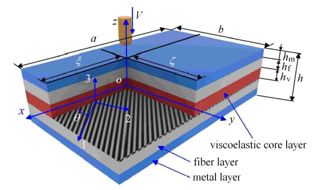
所建立的 VC-FMLPs 结构的冲击动力学模型如图1 所示,其长、宽、厚分别为 $a$,$b$,$h$. 其中,金属层厚度为 $h_{m}$,黏弹性层厚度为 $h_{v}$,每个纤维层厚度均相同且为 $h_{f}$. 首先,以结构受到球头型圆柱杆冲击激励时的中心位置为原点,以该类型层合板的中面为参考平面,并沿着厚度方向,建立 $o$-$xyz$ 坐标系. 图中的 1 代表纤维纵向,2 代表纤维横向,3 代表垂直于 1-2 平面的方向. 且纤维方向与整体坐标系 $x$ 轴的夹角为 $\theta$. 假设纤维增强复合薄板平行纤维方向的弹性模量为 $E_1 $,垂直纤维方向的弹性模量为 $E_2 $,1-2 平面内的剪切弹性模量为 $G_{12} $,1 方向作用应力引起 1, 2 方向应变的泊松比为 $\nu _{12} $,2 方向作用应力引起 1,2 方向应变的泊松比为 $\nu _{21} $. 金属层和黏弹性层的弹性模量分别 $E_{M} $ 和 $E_{V}$,剪切模量分别为 $G_{M} $ 和 $G_{V} $,泊松比分别为 $\nu _{M}$ 和 $\nu _{V}$. 另外,$V$ 为球头型圆柱杆在接触 VC-FMLPs 结构瞬间的速度,$\xi $ 和 $\zeta $ 为冲击位置参数,其取值范围分别为 $0 \leqslant \xi \leqslant a$, $0 \leqslant \zeta \leqslant b $.
图1
图1
嵌入黏弹性芯层的纤维金属混杂复合薄板理论模型
Fig. 1
The theoretical model of VC-FMLPs
1.2 本构关系
在冲击过程中,由于随着 VC-FMLPs 结构的逐步破坏,其参考平面不断变化. 因此,VC-FMLPs 结构的参考平面 $z_0$ 可表示为[24 ]
(1) $z_0 = \dfrac{\sum_{k = 1}^n {E_k h_k h_d } }{\sum_{k = 1}^n {E_k h_k } }$
其中,$E_k $ 为第 $k$ 层弹性模量,$h_k $ 为第 $k$ 层厚度,$h_d$ 为第 $k$ 层与球头型圆柱杆之间未被破坏层的总厚度.
由于冲击变形沿 $z$ 轴方向的位移 $w$ 远远大于沿 $x$ 轴和 $y$ 轴方向的位移 $u$ 和 $v$,因此忽略位移 $u$ 和 $v$. 根据经典层合板理论,正应变 $\varepsilon _z $ 和剪应变 $\gamma _{yz} $, $\gamma_{xz} $ 都为 0,即 $\varepsilon _z =\gamma _{yz} =\gamma _{xz} =0$. 结合冯$\cdot$卡门假设,用中面位移 $w_0 $ 表示 VC-FMLPs 结构任意点的应变[25 ] , 可写为
(2) $\left.\begin{array}{l} \varepsilon _x = \dfrac{1}{2}\left( {\dfrac{\partial w_0 }{\partial x}} \right)^2 - z\dfrac{\partial ^2w_0 }{\partial x^2} \\ \varepsilon _y = \dfrac{1}{2}\left( {\dfrac{\partial w_0 }{\partial y}} \right)^2 - z\dfrac{\partial ^2w_0 }{\partial y^2} \\ \gamma _{xy} = \dfrac{\partial w_0 }{\partial y}\dfrac{\partial w_0 }{\partial x} - 2z\dfrac{\partial ^2w_0 }{\partial x\partial y} \end{array}\!\!\right\}$
忽略应变率的影响[2 ,7 -10 ] ,则材料在第 $k$ 层主轴方向的应力-应变关系为
(3) $\left\{ \!\! \begin{array}{c} {{\sigma }'_1 } \\ {{\sigma }'_2 } \\ {{\sigma }'_{12} } \end{array} \!\! \right\}^{(k)} = \left[\!\! \begin{array}{ccc} {Q_{11} } & {Q_{12} } & 0 \\ {Q_{21} } & {Q_{22} } & 0 \\ 0 & 0 & {Q_{66} } \end{array} \!\! \right]^{(k)}\left\{ \!\! \begin{array}{c} {\varepsilon _1 } \\ {\varepsilon _2 } \\ {\gamma _{12} } \end{array} \!\! \right\}$
$ Q_{11} = Q_{22} = \dfrac{E_{V} }{1 - \nu _{V}^2 } , \ Q_{66} = \dfrac{E_{V} }{2\left( {1 + \nu _{V} } \right)} $
$ Q_{12} = Q_{21} = \dfrac{\nu _{V} E_{V} }{1 - \nu _{V}^2 } $
$ Q_{11} = Q_{22} = \dfrac{E_{M} }{1 - \nu _{M}^2 } , \ Q_{66} = \dfrac{E_{M}}{2\left( {1 + \nu _{M} } \right)} $
$ Q_{12} = Q_{21} = \dfrac{\nu _{M} E_{M} }{1 - \nu _{M}^2 } $
(4) $\left.\begin{array}{c} Q_{11} = \dfrac{E_1 }{1 - \nu _{12} \nu _{21} } , \ Q_{12} = \dfrac{\nu _{12} E_2 }{1 - \nu _{12} \nu _{21} } \\ Q_{22} = \dfrac{E_2 }{1 - \nu _{12} \nu _{21} } , \ Q_{66} = G_{12} ,\quad \nu _{21} = \nu _{12} \dfrac{E_2 }{E_1 } \end{array}\right\}$
当某一层失效后,失效层面内 1 方向,2 方向以及 3 方向上的应力 $\sigma _1^{f} $, $\sigma _2^{f}$,$\sigma _{12}^{f}$ 会分配到剩余层.根据各层刚度的不同,第 $k$ 层面内 1 方向,2 方向以及 3 方向分配得的应力 $\bar{\sigma }_1 $, $\bar{\sigma }_2 $, $\bar {\sigma }_{12} $ 为
(5) $ \left\{ \!\!\begin{array}{c} {\bar {\sigma }_1 } \\ {\bar {\sigma }_2 } \\ {\bar {\sigma }_{12} } \end{array} \!\! \right\}^{(k)} = \left\{ \!\! \begin{array}{c} {\sigma _1^{f} \dfrac{Q_{11}^{(k)} h_k }{K_1 h}} \\ {\sigma _2^{f} \dfrac{Q_{22}^{(k)} h_k }{K_2 h}} \\ {\sigma _{12}^{f} \dfrac{Q_{66}^{(k)} h_k }{K_{12} h}} \end{array}\!\! \right\} $
其中, $K_1 $, $K_2 $ 和 $K_{12}$ 为 VC-FMLPs 结构的等效刚度,其表达式为
(6) $K_1 = \dfrac{\bar {E}_1 }{1 - \bar {\nu }_{12}^{ 2} \dfrac{{\mathop{E}\limits^{ \_}}_2 }{{\mathop{E}\limits^{ \_}}_1 }} , K_2 = K_1 \dfrac{\bar {E}_2 }{{\mathop{E}\limits^{ \_}}_1 } , K_{12} = \bar {G}_{12}$
式中,$\bar {E}_1 $,$\bar {E}_2 $ 和 $\bar {G}_{12}$ 为 VC-FMLPs 结构的等效弹性模量,其表达式为
(7) $\bar {E}_1 = \dfrac{A_{11} - \dfrac{A_{12}^2 }{A_{22} }}{h} , \ \ \bar {E}_2 = \bar {E}_1 \dfrac{A_{22} }{A_{11} } , \ \ \bar {G}_{12} = \dfrac{A_{66} }{h}$
(8) $ \bar {\nu }_{12} = \dfrac{A_{12} }{A_{22} } , \ \ \bar {\nu }_{21} = \bar {\nu }_{12} \dfrac{\bar {E}_2 }{{\mathop{E}\limits^{ \_}}_1 }$
式中,$A_{ij}, B_{ij}, D_{ij} $ 分别为拉伸系数、拉伸弯曲耦合系数和弯曲系数, 可写为
(9) $ \left[ {A_{ij} , B_{ij} , D_{ij} } \right]^{T} = \int_{ - h / 2}^{h / 2} {\bar {Q}_{ij}^k \left[ {1,z,z^2} \right]^{T}} \text{d}z$
式中,$\bar {Q}_{ij}^k $ 为转轴刚度系数,用来表示考虑纤维层的材料主轴与 $ {x}$ 轴的夹角 $\theta $ 影响下的第 $ {k}$ 层板在整体坐标系下的应力-应变关系[26 -27 ] , 可写为
(10) $ \left\{ \!\! \begin{array}{c} {\sigma _x } \\ {\sigma _y } \\ {\sigma _{xy} } \end{array}\!\! \right\}^{(k)} = \left[\!\! \begin{array}{ccc} {\bar {Q}_{11} } & {\bar {Q}_{12} } & {\bar {Q}_{16} } \\ {\bar {Q}_{12} } & {\bar {Q}_{22} } & {\bar {Q}_{26} } \\ {\bar {Q}_{16} } & {\bar {Q}_{26} } & {\bar {Q}_{66} } \end{array}\!\! \right]^{(k)}\left\{\!\! \begin{array}{c} {\varepsilon _x } \\ {\varepsilon _y } \\ {\gamma _{xy} } \end{array}\!\! \right\}$
(11) $ \left. \!\!\begin{array}{c} \bar {Q}_{11} = Q_{11} \cos ^4\theta _k + 2(Q_{12} + 2Q_{66} )\sin ^2\theta _k \cos ^2\theta _k +\\ Q_{22} \sin ^4\theta _k \\ \bar {Q}_{12} = \left( {Q_{11} + Q_{22} - 4Q_{66} } \right)\sin ^2\theta _k \cos ^2\theta _k +\\ Q_{12} \left( {\sin ^4\theta _k + \cos ^4\theta _k } \right) \\ \bar {Q}_{22} = Q_{11} \sin ^4\theta _k + 2\left( {Q_{12} + 2Q_{66} } \right)\sin ^2\theta _k \cos ^2\theta _k +\\ Q_{22} \cos ^4\theta _k \\ \bar {Q}_{16} = \left( {Q_{11} - Q_{12} - 2Q_{66} } \right)\sin \theta _k \cos ^3\theta _k +\\ \left( {Q_{12} - Q_{22} + 2Q_{66} } \right)\sin ^3\theta _k \cos \theta _k \\ \bar {Q}_{26} = \left( {Q_{11} - Q_{12} - 2Q_{66} } \right)\sin ^3\theta _k \cos \theta _k +\\ \left( {Q_{12} - Q_{22} + 2Q_{66} } \right)\sin \theta _k \cos ^3\theta _k \\ \bar {Q}_{66} = \left( {Q_{11} + Q_{22} - 2Q_{12} - 2Q_{66} } \right)\sin ^2\theta _k \cos ^2\theta _k +\\ Q_{66} \left( {\sin ^4\theta _k + \cos ^4\theta _k } \right) \end{array}\!\!\right\}$
式中,$\theta$ 为第 ${k}$ 层板的纤维方向与整体坐标系 ${x}$ 轴的夹角.
结合式 (3) 和式 (5),就可以得到第 $k$ 层面内 1 方向,2 方向以及 3 方向实际应力 $\sigma_1 $, $\sigma _2 $, $\sigma _{12} $ 为
(12) $ \left\{ \!\! \begin{array}{c} {\sigma _1 } \\ {\sigma _2 } \\ {\sigma _{12} } \end{array} \!\! \right\}^{(k)} = \left\{ \!\! \begin{array}{c} {{\sigma }'_1 } \\ {{\sigma }'_2 } \\ {{\sigma }'_{12} } \end{array}\!\! \right\}^{(k)} + \left\{ \!\! \begin{array}{c} {\bar {\sigma }_1 } \\ {\bar {\sigma }_2 } \\ {\bar {\sigma }_{12} } \end{array}\!\! \right\}^{(k)}$
1.3 失效准则
在文献[28 ,29 ,30 ] 提出的低速冲击下层合板结构损伤失效准则的基础上,利用逐渐累积损伤分析方法,对于金属层,可应用 Von Mises 等效应力失效准则[28 ]
(13) $ \dfrac{\sigma _1^2 + \sigma _2^2 - \sigma _1 \sigma _2 + 3\sigma _{12}^2 }{\sigma _{M}^{e} } = 1$
其中,$\sigma _{M}^{\rm e}$ 为金属层材料的等效屈服应力,低速冲击时认为金属层达到屈服抗拉强度,就已经失去承载能力,不考虑之后塑性变形对结构的影响.
对于纤维层,应用 Tsai-Hill 应力失效准则[29 ]
(14) $ \left( {\dfrac{\sigma _1 }{X_{T} }} \right)^2 + \left( {\dfrac{\sigma _2 }{Y_{T} }} \right)^2 - \dfrac{\sigma _1 \sigma _2 }{X_{T} ^2} + \left( {\dfrac{\sigma _{12} }{S_{f} }} \right)^2 = 1$
其中,$X_{T}$ 为纤维纵向拉伸强度,$Y_{T}$ 为纤维横向拉伸强度,$S_{f}$ 为纤维的剪切强度.
对于黏弹性层,应用指数 Drucker-Prager 应力失效准则[30 ]
(15) $ \dfrac{ (\sigma_1-\sigma_2)^2+(\sigma_1-\sigma_{12})^2+(\sigma_2-\sigma_{12})^2 }{2(\sigma^{e}_{\rm v})^2} =1$
其中,$\sigma^{e}_{v}$ 为黏弹性层材料的等效屈服应力,可表示为
(16) $ \sigma^{e}_{v} = \left[ {\lambda \left( {\sigma _{v}^{T} } \right)^2 - 3\left( {\lambda - 1} \right)\sigma _{v}^{T} \sigma _{v}^{A} } \right]^{1 / 2}$
式中,$\sigma _{v}^{T}$ 为黏弹性层的屈服抗拉强度,$\sigma _{v}^{A}$ 为主应力表示的流体静应力,$\lambda $ 为流体静应力敏感系数. $\lambda$ 的值由两种或两种以上不同应力状态下的屈服应力确定,低速冲击状态下,主要考虑屈服抗拉强度 $\sigma _{v}^{T}$ 和屈服剪切强度 $\sigma _{v}^{s}$. 其各自表达式为
(17) $\sigma_{v}^{A}= \dfrac{1}{3}(\sigma _1 + \sigma _2 + \sigma _{12} )$
(18) $\lambda = 3(\sigma_{v}^{s} )^2 / (\sigma_{v}^{T})^2$
1.4 位移方程
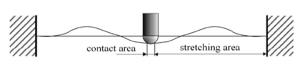
在与球头型圆柱杆冲击接触过程中,VC-FMLPs 结构将形成两个变形的区域,分别称其为接触区域与拉伸区域,如图2 所示. 假设冲击过程中,损伤仅发生在接触区域内. 在此区域内,需计算结构因塑性变形 (及其损伤) 消耗的能量以及因弹性变形产生的应变能;在拉伸区域内,只需计算因弹性变形产生的应变能.
图2
图2
VC-FMLPs 结构变形区域
Fig. 2
The deformation region of FMLPs
对于接触区域,其主要由球头型圆柱杆形状决定,其范围可看作由冲击中心位置到接触半径,即 $0 \leqslant x \leqslant R$, $0 \leqslant y \leqslant R $. 考虑到接触半径相对于该类型层合板的尺寸非常小,可将该接触区域近似看成一个平面. 在这个范围内,中面位移 $w_0 (x,y)$ 的表达式为
(19) $w_0 (x,y) = w_{\max }$
其中,$w_{\max } $为冲击中心处的最大位移.
对于拉伸区域,其范围可看作由接触半径到结构约束边界组成,即 $R \leqslant x\leqslant \max \left\{ {\xi , a - \xi } \right\}$,$R \leqslant y \leqslant\max \left\{ {\zeta , b - \zeta } \right\}$. 对于图1 所示的四边固支边界下的 VC-FMLPs 结构,$w_0 (x,y)$ 有如下关系式
(20) $w_0 = 0 , \ \ \dfrac{\partial w_0 }{\partial x} \approx 0 , \ \ \dfrac{\partial w_0 }{\partial y} \approx 0$
为了解释不同材料层对 VC-FMLPs 结构中面位移的贡献,改进文献[31 ] 中的位移公式,引入金属体积分数 $v_{\rm m}$,纤维层体积分数 $v_{f}$,黏弹性层体积分数 $v_{v}$,并使其满足式 (20) 中的边界条件
(21) $ w_0 (x,y) = w_{M} v_{m} \left( {1 - \dfrac{x}{\xi }} \right)^2\left( {1 - \dfrac{y}{\zeta }} \right)^2 + \\ w_{f} v_{f} \left[ {1 - \left( {\dfrac{x}{\xi }} \right)^2} \right]\left[ {1 - \left( {\dfrac{y}{\zeta }} \right)^2} \right] + \\ w_{v} v_{\rm v} \left( {1 - \dfrac{x}{\xi }} \right)^2\left( {1 - \dfrac{y}{\zeta }} \right)^2$
(22) $w_{M} = \dfrac{w_{\max } }{\left( {1 - \dfrac{R}{\xi }} \right)^2\left( {1 - \dfrac{R}{\zeta }} \right)^2}$
(23) $w_{f} = \dfrac{w_{\max } }{\left[ {1 - \left( {\dfrac{R}{\xi }} \right)^2} \right]\left[ {1 - \left( {\dfrac{R}{\zeta }} \right)^2} \right]}$
(24) $w_{v} = \dfrac{w_{\max } }{\left( {1 - \dfrac{R}{\xi }} \right)^2\left( {1 - \dfrac{R}{\zeta }} \right)^2}$
在利用模型计算获得了中面位移后,将其代入式 (2)、式 (3)、式 (5) 和式 (12) 来获得变形最大位置处 (在冲击中心位置处,近似取 $x=R$, $y=R$ 处) 应力,并进一步应用 1.3 部分对应的失效准则来判别某层是否发生失效. 如果式 (13) 或式 (14) 或式 (15) 对应的左侧表达式大于 1,则认为该层发生了损伤 (此时,可认为满足了失效准则要求,并可将对应的接触区域内刚度设置为零);如果没有发生失效,则将中面位移对应的 $w_{\max } $ 进行更新,并在获得新的中面位移基础上,重复利用式 (13) 或式 (14) 或式 (15) 进行判别,直到满足失效准则的要求为止.
2 冲击响应求解
2.1 冲击接触力的计算
(25) $T=\dfrac 12 MV^2_0$
(26) $U = \dfrac{1}{2}\int_x {\int_y {\int_z {\sigma _x \varepsilon _x + \sigma _y \varepsilon _y + \sigma _{xy} \gamma _{xy} } } } \text{d} x \text{d} y \text{d}z$
将式 (2)、式 (9) 和式 (10) 代入式 (26) 中,可得到 VC-FMLPs 结构由拉伸变形产生的应变能 $U_{m}$
(27) $\begin{array}{c} U_{m} = \int_0^\xi {\int_0^\zeta { \Bigg [\dfrac{1}{8}A_{11} } } \left( {\dfrac{\partial w}{\partial x}} \right)^4 + \dfrac{1}{4}A_{12} \left( {\dfrac{\partial w}{\partial x}} \right)^2\left( {\dfrac{\partial w}{\partial y}} \right)^2+\\ \dfrac{1}{8}A_{22} \left( {\dfrac{\partial w}{\partial y}} \right)^2 + \dfrac{1}{2}\left[ {A_{16} \left( {\dfrac{\partial w}{\partial x}} \right)^2 + A_{26} \left( {\dfrac{\partial w}{\partial y}} \right)^2} \right]\dfrac{\partial w}{\partial x}\dfrac{\partial w}{\partial y} +\\ \dfrac{1}{2}A_{66} \left( {\dfrac{\partial w}{\partial x}\dfrac{\partial w}{\partial y}} \right)^2 \Bigg ] \text{d} x \text{d} y\end{array}$
VC-FMLPs 结构拉伸弯曲耦合应变能 $U_{c}$ 为
(28) $\begin{array}{c} U_{c} = - \int_0^\xi {\int_0^\zeta { \Bigg [\dfrac{1}{4}B_{11} } } \left( {\dfrac{\partial w}{\partial x}} \right)^2\dfrac{\partial ^2w}{\partial x^2} +\\ \dfrac{1}{2}B_{12} \left[ {\left( {\dfrac{\partial w}{\partial y}} \right)^2\dfrac{\partial ^2w}{\partial x^2} + \left( {\dfrac{\partial w}{\partial x}} \right)^2\dfrac{\partial ^2w}{\partial y^2}} \right] +\\ \dfrac{1}{4}B_{22} \left( {\dfrac{\partial w}{\partial y}} \right)^2\dfrac{\partial ^2w}{\partial y^2} + \\ B_{16} \left[ {\dfrac{\partial ^2w}{\partial x^2}\dfrac{\partial w}{\partial x}\dfrac{\partial w}{\partial y} + \left( {\dfrac{\partial w}{\partial x}} \right)^2\dfrac{\partial ^2w}{\partial x\partial y}} \right] +\\ B_{26} \left[ {\dfrac{\partial ^2w}{\partial y^2}\dfrac{\partial w}{\partial x}\dfrac{\partial w}{\partial y} + \left( {\dfrac{\partial w}{\partial y}} \right)^2\dfrac{\partial ^2w}{\partial x\partial y}} \right] +\\ 2B_{66} \dfrac{\partial ^2w}{\partial x\partial y}\dfrac{\partial w}{\partial x}\dfrac{\partial w}{\partial y} \Bigg ] \text{d} x \text{d} y\end{array}$
VC-FMLPs 结构弯曲产生的应变能 $U_{b} $ 为
(29) $\begin{array}{c} U_{b} = \int_0^\xi {\int_0^\zeta { \Bigg [\dfrac{1}{2}D_{11} } } \left( {\dfrac{\partial ^2w}{\partial x^2}} \right)^4 + D_{12} \dfrac{\partial ^2w}{\partial x^2}\dfrac{\partial ^2w}{\partial y^2}+\\ \dfrac{1}{2}D_{22} \left( {\dfrac{\partial ^2w}{\partial y^2}} \right)^2 + 2\left( {D_{16} \dfrac{\partial ^2w}{\partial x^2} + D_{26} \dfrac{\partial ^2w}{\partial y^2}} \right)\dfrac{\partial ^2w}{\partial x\partial y}+\\ \dfrac{1}{2}D_{66} \dfrac{\partial ^2w}{\partial x\partial y}^2 \Bigg ] \text{d} x \text{d} y \end{array}$
这里,需要说明的是,式 (27),式 (28) 和式 (29) 只是对 VC-FMLPs 结构在 ${xoy}$ 面内的第一象限积分后的应变能结果,结构的总应变能需要对 4 个象限要分别积分,并进行叠加才可获得.
(30) $W = Fw_{\max }$
VC-FMLPs 结构总势能 $U_{s}$ 表达式为
(31) $U_{s} = U_{m} + U_{c} + U_{b} -W$
当 $\partial U_{s} / \partial w_{\max } = 0$ 时,$U_{s }$ 会获得最大值,此时,可计算获得冲击接触力 $F$
(32) $F = \partial U_{m} / \partial w_{\max } + \partial U_{c} / \partial w_{\max } + \partial U_{b} / \partial w_{\max }$
2.2 失效模式
首先,为了求解方便,引入冲击"失效事件"的概念[32 ] ,假设该事件是由冲击造成的 VC-FMLPs 结构在接触区域的分层损伤和断裂效应引发的,则每个失效事件 $j$ 吸收的总应变能 $U_{j}$ 可表示为
(33) $U_j = (U_{m}^j + U_{c}^j + U_{b}^j ) - (U_{m}^{j - 1} + U_{c}^{j - 1} + U_{b}^{j - 1} )$
其中,$U_{m}^j , U_{c}^j , U_{b}^j$ 代表第 $j$ 个失效事件发生时的拉伸应变能,拉伸弯曲耦合应变能和弯曲应变能,$U_{m}^{j - 1} , U_{c}^{j - 1} , U_{b}^{j - 1} $ 为前一个失效事件对应的拉伸应变能,拉伸弯曲耦合应变能和弯曲应变能.
参考文献[32 ] ,可获得 $x=R_{j}$, $y =0$ 处变形协调条件,并得到下列等式条件
(34) $ \sqrt {R_{\max }^2 - R_j^2 } + w_{\max } - R_{\max } = w_{M} v_{m} \left( {1 - \dfrac{R_j }{\xi }} \right)^2 +\\ w_{f} v_{f} \left[ {1 - \left( {\dfrac{R_j }{\xi }} \right)^2} \right] + w_{v} v_{v} \left( {1 - \dfrac{R_j }{\xi }} \right)^2 \\ $
其中,$R_{j}$ 为第 $j$ 个失效事件时的接触半径,$R_{\max}$ 为球头型圆柱杆球头半径. 这样,$R_{j}$ 就通过式 (34) 求解获得.
第 $j$ 次失效事件中,因分层损伤消耗的能量 $T_{d}^j $ 为
(35) $T_{d}^j = \dfrac{\pi \bar {E}_1^j hG_{II}^2 }{9\left[ {1 - (\bar {\nu }_{12}^j )^2} \right]\left( {\sigma _{IL} } \right)^2} + \dfrac{\pi \bar {E}_2^j hG_{II}^2 }{9\left[ {1 - (\bar {\nu }_{21}^j )^2} \right]\left( {\sigma _{IL} } \right)^2}$
其中,$G_{II} $ 为 VC-FMLPs 结构的第二类层间断裂能量释放率[33 ] ,$\sigma_{IL} $ 为层间剪切强度. $\bar {E}_1^j $,$\bar {E}_2^j$ 为失效事件 $j$ 发生时 1 和 2 方向对应的等效弹性模量,$\bar {\nu }_{12}^j $,$\bar {\nu }_{21}^j $ 为等效泊松比.
第 $j$ 次失效事件中,各层材料由于断裂效应产生的能量 $T_{f}^j $ 为
(36) $T_{f}^j = w_{\max }^j \pi e_t R_j^2 / 3$
其中,$e_t $ 为某层能量密度. 对于纤维层、金属层以及黏弹性层,其能量密度 $e_t^{f} $, $e_t^{m}$ 和 $e_t^{v} $ 分别为
(37) $ \left. \begin{array}{l} e_t^{f} = \dfrac{1}{2}\sigma _{f}^u \varepsilon _{f}^u \\ e_t^{m} = \dfrac{1}{2}\sigma _{m}^y \varepsilon _{m}^y + \left( {\sigma _{m}^u + \sigma _{m}^y } \right)\dfrac{\varepsilon _{m}^u - \varepsilon _{m}^y }{2} \\ e_t^{v} = \dfrac{1}{2}\sigma _{v}^y \varepsilon _{v}^y + \left( {\sigma _{v}^u + \sigma _{v}^y } \right)\dfrac{\varepsilon _{v}^u - \varepsilon _{v}^y }{2} \end{array}\!\!\right\}$
其中,$\sigma _{f}^u $ 和 $\varepsilon _{f}^u $ 为纤维层应力极限和纵向极限应变;$\sigma _{m}^y$和$\sigma _{m}^u $ 为金属层屈服抗拉强度和极限抗拉强度,其对应的应变为 $\varepsilon _{m}^y$ 和 $\varepsilon _{m}^u $;$\sigma _{v}^y $ 和 $\sigma _{v}^u$ 为黏弹性层屈服抗拉强度和极限抗拉强度,其对应的应变为 $\varepsilon _{v}^y $ 和 $\varepsilon _{\rm v}^u $.
这样,可获得每个失效事件 $j$ 消耗的总能量 $T_{a}^j $
(38) $T_{a}^j = U_j + T_{d}^j + T_{f}^j$
进一步,由能量守恒定律可获得每次失效事件 $j$ 发生后的冲击速度的表达式
(39) $V_{j + 1} = \sqrt { MV_j^2 - 2T_{a}^j / M }$
另外,根据参考文献[31 ] ,采用一个单自由度弹簧-质量-阻尼模型来描述 VC-FMLPs 结构在球头型圆柱杆冲击下的整个过程. 则第$j$次失效事件中的接触力 $F_j$ 可由动力学方程表示
(40) $F_j = (M + m_{e}^j )\dfrac{\partial ^2w_{\max }^j }{\partial t^2} + C_{s}^j \dfrac{\partial w_{\max }^j }{\partial t} + K_{s}^j w_{\max }^j$
其中,$M$ 为球头型圆柱杆质量,$m_{e}^j $ 和 $w_{\max }^j $ 为第 $j$ 次失效事件时 VC-FMLPs 结构受冲击作用影响的的等效质量和冲击中心处最大位移,$K_{s}^j $, $C_{s}^j $ 为分别为结构整体剪切刚度和黏滞阻尼系数.
(41) $F_j - K_{s}^j w_{\max }^j - C_{s}^j \dot {w}_{\max }^j = (M + m_{e}^j )\dot {V}_j$
$ \dot {V}_j = \dfrac{\left| {V_j - V_{j - 1} } \right|}{t_j - t_{j - 1} } , \ \ \dot {w}_{\max }^j = \dfrac{w_{\max }^j - w_{\max }^{j - 1} }{t_j - t_{j - 1} } \\ K_{s}^j = K_{12}^j , \ \ C_{s}^j = 2\varsigma _j \sqrt {K_{s}^j (M + m_{s}^j )} $
$K_{12}^j$ 为失效事件 $j$ 发生时结构整体剪切刚度,$\varsigma _j $ 第失效事件 $j$ 发生时的等效阻尼比.$V_{j}$, $V_{j - 1}$, $w_{\max }^j $, $w_{\max }^{j - 1} $ 以及 $t_{j}$ 和 $t_{j -1}$ 分别代表了第 $j$ 次失效事件和第 $j -1$ 次失效事件中的速度,冲击中心处最大位移和时间.
第 $j$ 次失效事件对应的动能 $T_{c}^j $ 可表示为
(42) $ T_{c}^j = 2\mathop{\displaystyle\iint}\limits_{A - A_j } \Bigg[\dfrac{\rho _{a} (\dot {w}_{\max }^j )^2} {\left( {1 - \dfrac{2R_j }{a}} \right)^2\left( {1 - \dfrac{2R_j }{b}} \right)^2}\cdot\\ \left( {1 - \dfrac{2x}{a}} \right)^2\left( {1 - \dfrac{2y}{b}} \right)^2 \Bigg ] \text{d}A + \dfrac{1}{2}\pi R_j^2 \rho _{a} (\dot {w}_{\max }^j )^2 $
其中,$\rho _{a}$ 为 VC-FMLPs 结构的面密度,$A$ 为其整体积分区域,$A_{j}$ 为接触区域.
由于可近似认为 $T_{c}^j = m_{e}^j (\dot {w}_{\max }^j )^2 / 2$,则 $m_{e}^j $ 可表示为
(43) $m_{e}^j = \pi R_j^2 \rho _{a} + \dfrac{1}{9}(a - 2R_j )(b - 2R_j )\rho _{a}$
如此,可根据式 (41),确定失效事件 $j$ 发生的时间 $t_j $
(44) $t_j = \dfrac{(M + m_{e}^j )\left| {V_j - V_{j - 1} } \right| + C_{s}^j (w_{\max}^j - w_{\max }^{j - 1} )}{F_j - K_{s}^j w_{\max }^j } + t_{j - 1}$
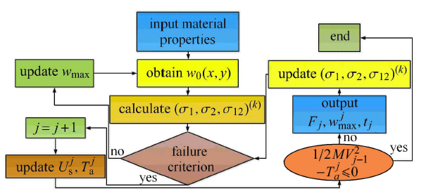
至此,就实现了 VC-FMLPs 结构冲击动态响应的理论求解,其详细的分析流程如图3 所示. 当失效事件 $j$ 发生时,通过式 (33) 求解结构系统吸收的总应变能 $U_j$,通过式 (35) 和式 (36) 求解接触区域,因分层损伤消耗的能量 $T_{d}^j$ 和塑性变形消耗的能量 $T_{f}^j $,进而求解冲击接触力 $F_j $、位移 $w_{\max }^j$ 和失效事件 $j$ 发生的时间 $t_j $,直至球头型圆柱杆冲击能量消耗为零,输出计算结果.
图3
图3
低速冲击激励下 VC-FMLPs 结构动态响应分析流程图
Fig. 3
Flow chart of dynamic response analysis of VC-FMLPs under low-velocity impact excitation
3 实验验证
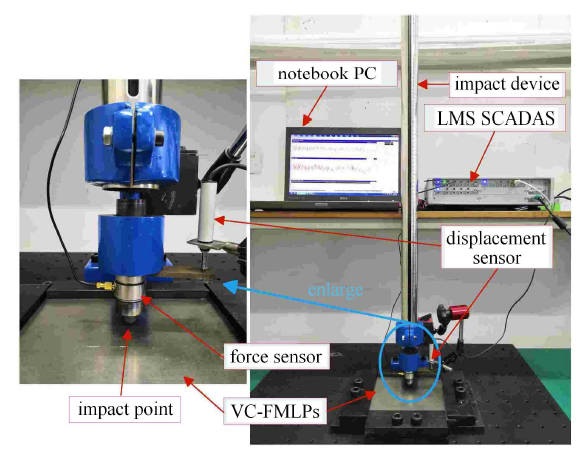
图4 给出了自行设计的 VC-FMLPs 结构落锤冲击试验系统,落锤质量为 1 kg,刚性冲头的顶端被设计成半球形状 (直径 8.0 mm). 在冲击测试过程中,通过磁力表座固定在冲头上的 LSM 位移传感器和嵌入式动态力传感器 (型号为联能 CL-YD-305),并利用 LMS 数据采集仪和笔记本工作站,可实时采集并记录结构在低速冲击下的冲击接触力和响应数据. 试验系统经过 "江苏联能电子技术有限公司" 和 "KISTLER" 专业技术员的调试和校准,并在正式实验前进行多次预实验,保证了实验结果的可重复性.
图4
图4
落锤低速冲击试验设备
Fig. 4
Drop weight impact tester
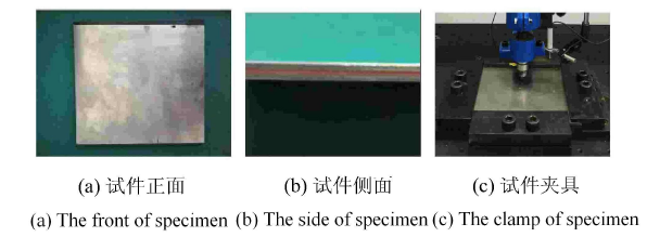
以嵌入 Zn33 黏弹性芯层的 TA2 钛合金混杂T300 碳纤维/树脂基层合板为对象,通过夹具夹紧其四边,夹持后长、宽、厚为 170 mm $\times $ 160 mm $\times$ 2.6 mm,如图5 所示. 其中金属外层厚度为 0.3 mm,$E_{M} =$ 108 GPa,$\nu _{M} =0.3 $,$\rho _{M} = 4150$ kg/m$^3$,$\sigma _{M}^{e} = 600$ MPa;纤维层为对称正交铺设 $[0^ \circ / 90^ \circ / 0^ \circ / 90^ \circ ]$ 的 TC300 碳纤维/E21 环氧树脂,共有 9 层,$E_{1} = 136$ GPa, $E_{2} =$ $7.92$ GPa, $G_{12} =3.39$ GPa,$\nu _{12} = 0.32$,$\rho _{f} = 1780$ kg/m$^3$, $X_{T}=2210$ MPa,$ Y_{\rm T}=49$ MPa,$S_{f} = 135$ MPa;黏弹性层厚度为 1 mm,$E_{V} = 5$ MPa,$\nu _{V} = 0.3$,$\rho_{V} = 4510$ kg/m$^3$,$\sigma _{v}^{T} = 7$ MPa.
图5
图5
VC-FMLPs 结构试验件及夹具
Fig. 5
Test piece and fixtures of VC-FMLPs
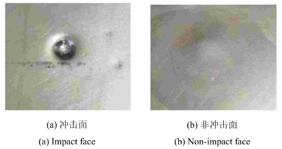
在落锤高度为 0.6 m 和 1 m 处 (即冲击能量为5.9 J 和 9.8 J 时),分别开展冲击实验,图6 给出了测试获得的 VC-FMLPs 结构的冲击接触力、位移响应和冲击载荷-位移曲线.为了方便与实验数据进行对比,将利用第 1 部分建立的理论模型计算获得的分析结果也一并绘制在图7 上,还以图中的峰值结果作为统计,给出了相应的计算相对误差.另外,以冲击能量达到 9.8 J 为例,图7 给出了结构在冲击面和非冲击面产生的损伤照片.
图6
图6
理论和测试获得的低速冲击下 VC-FMLPs 结构的冲击接触力时程曲线、位移响应曲线和冲击载荷-位移曲线
Fig. 6
Impact contact force time-history curve, displacement response curve and load-displacement curve of VC-FMLPs under low-velocity impact obtained by theory and test
图7
图7
冲击能量为 9.8 J 时 VC-FMLPs 结构的冲击损伤
Fig. 7
Impact damage of VC-FMLPs under the impact energy of 9.8 J
通过对上述结果进行分析可知:利用该理论模型,计算获得的 VC-FMLPs 结构冲击下的 冲击接触力时程曲线、位移响应以及冲击载荷-位移曲线与实验结果的变化趋势吻合较好,且关注的曲线上峰值点的计算误差最大不超过 9% (详见图6 ),进而验证了所建立的动态响应预测模型及其分析方法的正确性,可以利用该模型对 VC-FMLPs 结构的冲击响应进行较为可靠的预测和分析. 另外,需要说明的是,利用该模型完成上述计算的时间在3 min以内,相对于商用软件 ANSYS 的 LS-DYNA 模块,大大提高了计算效率 (其通常花费 3$\sim $5 h).
但仍有必要对模型的局限性问题进行分析: (1)建模时忽略了已失效层在冲击过程中的持续损伤累积,这也是计算误差的来源之一;(2)认为每个失效事件发生时,将接触区域内刚度整体清零,在后续的研究中,应在考虑损伤区域的剩余刚度;(3)由于该模型没有考虑应变率等因素的影响,因而不适合预测高速冲击问题;(4)由于模型需要进行足够次数的迭代,才能进行高精度预测,如果是太低速的冲击,则会因迭代次数过少而影响计算精度.因此,参考相关文献的假设条件[2 ] ,推荐该模型适用的冲击速度范围为2$\sim $10 m/s.
4 结论
本文建立了低速冲击激励下嵌入黏弹性阻尼芯层的纤维金属混杂层合板动态响应预测模型,并对其分析获得的冲击接触力、位移响应以及冲击载荷-位移曲线进行了测试验证. 结果表明,理论计算与获得的上述冲击参数的变化趋势与实验吻合较好,且关注的曲线上峰值点的计算误差最大不超过 9%,进而验证了理论模型和分析方法的正确性. 另外,相对于 ANSYS 的 LS-DYNA 模块,该模型大大提高了计算效率,可为复杂层合板结构动态冲击问题的高效求解提供一种新思路和新手段.
参考文献
View Option
[1]
Carrillo JG Cantwell WJ . Mechanical properties of a novel fiber-metal laminate based on a polypropylene composite
Mechanics of Materials 2009 ,41 (7 ):828 -838
[本文引用: 1]
[2]
Chai GB Manikandan P . Low velocity impact response of fibre-metal laminates-A review
Composite Structures 2014 ,107 :363 -381
[本文引用: 2]
[3]
侯淑娟 , 梁慧妍 , 汪全中 等 . 基于迭代法的非线性弹性均质化研究
力学学报 , 2018 ,50 (4 ):135 -144
[本文引用: 1]
( Hou Shujuan Liang Huyan Wang Quanzhong , et al . Study on nonlinear elastic homogenization with iterative method
Chinese Journal of Theoretical and Applied Mechanics 2018 ,50 (4 ):135 -144 (in Chinese))
[本文引用: 1]
[4]
李晖 , 孙伟 , 许卓 等 . 纤维增强复合薄板振动测试与分析方法 . 北京 : 机械工业出版社 , 2019
[本文引用: 1]
( Li Hui Sun Wei Xu Zhuo , et al . Methods for Vibration Testing and Analysis of Fiber-Reinforced Composite . Beijing : China Machine Press , 2019 (in Chinese))
[本文引用: 1]
[5]
Vo TP Guan ZW Cantwell WJ , et al . Modelling of the low-impulse blast behaviour of fibre-metal laminates based on different aluminium alloys
Composites Part B: Engineering 2013 ,44 (1 ):141 -151
[6]
许卓 , 李晖 , 薛鹏程 等 . 悬臂纤维金属复合薄板固有特性分析及验证
东北大学学报 , 2018 ,39 (12 ):1737 -1742
( Xü Zhuo Li Hui Xue Pengcheng , et al . Natural characteristics analysis and validation of fiber metal laminates thin plates under cantilever boundary
Journal of Northeastern University 2018 ,39 (12 ):1737 -1742 (in Chinese))
[7]
陈倩 , 张汉哲 , 吴钦 等 . 复合材料水翼水动力与结构强度特性数值研究
力学学报 , 2019 ,51 (5 ):1350 -1362
[本文引用: 1]
( Chen Qian Zhang Hanzhe Wu Qin , et al . The numerical investifation on hydrodynamic and structural strength of a composite hydrofoil
Chinese Journal of Theoretical and Applied Mechanics 2019 ,51 (5 ):1350 -1362 (in Chinese))
[本文引用: 1]
[8]
张洁皓 , 段晨 , 侯玉亮 等 . 基于渐进均匀化的平纹编织复合材料低速冲击多尺度方法
力学学报 , 2019 ,51 (5 ):837 -846
[本文引用: 1]
( Zhang Jiehao Duan Chen Hou Yuliang , et al . Multi-scale method of plain woven composites subjected to low velocity impact based on asymptotic homogenization
Chinese Journal of Theoretical and Applied Mechanics 2019 ,51 (5 ):837 -846 (in Chinese))
[本文引用: 1]
[9]
Vlot A . Low-velocity impact loading on fibre reinforced aluminium laminates(ARALL) and other aircraft sheet materials. [PhD Thesis]
Delft: Delft University of Technology , 1991
[本文引用: 1]
[10]
Vlot A . Impact properties of fibre metal laminates
Composites Engineering 1993 ,3 (10 ):911 -927
DOI
URL
[本文引用: 2]
[11]
Vlot A . Impact loading on fibre metal laminates
International Journal of Impact Engineering 1996 ,18 (3 ):291 -307
DOI
URL
[12]
Vlot A Kroon E Rocca GL . Impact response of fiber metal laminates
Key Engineering Materials 1998 , 141-143 :235 -276
[本文引用: 1]
[13]
Davies GAO Zhang X Zhou G , et al . Numerical mod-elling of impact damage
Composites 1994 ,25 (5 ):350
[本文引用: 1]
[14]
Payeganeh GH Ghasemi FA Malekzadeh K . Dynamic response of fiber-metal laminates (FMLs) subjected to low-velocity impact
Thin-Walled Structures 2010 ,48 (1 ):62 -70
DOI
URL
[本文引用: 1]
[15]
Yiming F Yiqi M Yanping T . Damage analysis and dynamic response of elasto-plastic laminated composite shallow spherical shell under low velocity impact
International Journal of Solids and Structures 2010 ,47 (1 ):126 -137
DOI
URL
[本文引用: 1]
AbstractBased on the elasto-plastic mechanics, the damage analysis and dynamic response of an elasto-plastic laminated composite shallow spherical shell under low velocity impact are carried out in this paper. Firstly, a yielding criterion related to spherical tensor of stress is proposed to model the mixed hardening orthotropic material, and accordingly an incremental elasto-plastic damage constitutive relation for the laminated shallow spherical shell is founded when a strain-based Hashin failure criterion is applied to assess the damage initiation and propagation. Secondly, using the presented constitutive relations and the classical nonlinear shell theory, a series of incremental nonlinear motion equations of orthotropic moderately thick laminated shallow spherical shell are obtained. The questions are solved by using the orthogonal collocation point method, Newmark method and iterative method synthetically. Finally, a modified elasto-plastic contact law is developed to determine the normal contact force and the effect of damage, geometrical parameters, elasto-plastic contact and boundary conditions on the contact force and the dynamic response of the structure under low velocity impact are investigated.]]>
[16]
毛贻齐 . 低速冲击下损伤层合/功能梯度板壳的非线性动力学研究. [博士论文]
长沙:湖南大学 , 2011
[本文引用: 1]
( Mao Yiqi . Nonlinear dynamic analysis for laminated/FGM plates and shells with damage under low velocity impact. [PhD Thesis]
Changsha: Hunan University , 2011 (in Chinese))
[本文引用: 1]
[17]
Starikov R . Assessment of impact response of fiber metal laminates
International Journal of Impact Engineering 2013 ,59 :38 -45
DOI
URL
[本文引用: 1]
[18]
陈勇 . 冲击载荷下纤维金属层板损伤行为及动态响应特性研究. [博士论文]
哈尔滨:哈尔滨工业大学 , 2014
[本文引用: 1]
( Chen Yong . Research on characteristics of damage behavior and dynamic response of fibre-metal laminate under impact load. [PhD Thesis]
Harbin: Harbin Institute of Technology , 2014 (in Chinese))
[本文引用: 1]
[19]
Jones N . Note on the impact behaviour of fibre-metal laminates
International Journal of Impact Engineering 2017 ,108 :147 -152
DOI
URL
[本文引用: 1]
[20]
Cupia P Nizio J . Vibration and damping analysis of a three-layered composite plate with a viscoelastic mid-layer
Journal of Sound and Vibration 1995 ,183 (1 ):99 -114
DOI
URL
[本文引用: 1]
[21]
胡明勇 , 王安稳 . 纤维增强黏弹性复合材料层合板的自由振动和应力分析
工程力学 , 2010 ,27 (8 ):10 -14
URL
[本文引用: 1]
基于Reddy分层理论推导出纤维增强粘弹性复合材料层合板的动力学方程,得到了其自由振动频率和损耗因子;分析了自由振动时,纤维体积含量和纤维增强层厚度对自然频率和损耗因子的影响;且计算出了协调的横向应力,数值结果分析表明:结构频率和损耗因子随纤维体积含量的增加而增加;阻尼材料参数对结构损耗因子和横向应力影响较大,且阻尼材料模量存在最佳值;高阶模态下,较高的横向正应力是层合板脱层的主要因素。
( Hu Mingyong Wang Anwen . Free vibration and stresses analysis of fiber-reinforced viscoelastic composite laminated plates
Engineering Mechanics 2010 ,27 (8 ):10 -14 (in Chinese))
URL
[本文引用: 1]
Based on the theory of Reddy layerwise, the governing equations of fiber-reinforced viscoelastic composite laminates are derived. The frequency and loss factor of free vibration are obtained. The variation of the natural frequency and loss factor along with the fiber volume fraction or the thickness of fiber-reinforced layer is analyzed. The harmonious transverse stresses are calculated. The results of numerical analysis show that the structure loss factor of damping laminated shells increases with the increase of the volume fraction of fibers. The parameter of the damping layer has great influence on the structure loss factor and transverse stresses; there shall be an optimal value about the modulus of damping material. The main factor of delamination is that transverse stresses are very high in a high-order mode.
[22]
Malekzadeh K Khalili MR Olsson R , et al . Higher-order dynamic response of composite sandwich panels with flexible core under simultaneous low-velocity im-pacts of multiple small masses
International Journal of Solids and Structures 2006 ,43 (22-23 ):6667 -6687
DOI
URL
[本文引用: 1]
[23]
Shariyat M Hosseini SH . Eccentric impact analysis of pre-stressed composite sandwich plates with viscoelastic cores: A novel global-local theory and a refined contact law
Composite Structures 2014 ,117 :333 -345
DOI
URL
[本文引用: 1]
A novel double superposition power-exponential global-local theory and a refined contact law are developed to investigate eccentric low-velocity impact responses of rectangular sandwich plates with viscoelastic cores. The continuity conditions of the transverse normal and shear stresses at the interfaces between layers is satisfied a priori. Stiffness of the underneath layers is considered in the contact law as well, for the first time. The non-linear integro-differential governing equations are solved by a second-order finite element and a special numerical time integration procedure. Effects of the pre-stresses on the indentation and contact force are investigated for the first time. Moreover, effects of the eccentricity on the impact responses of the sandwich plates are discussed in detail, for the first time. Verification of the results is accomplished through comparing present results with experimental results of a known reference. Results show that in the eccentric impacts, the contact force and the absorbed energy increase. Therefore, the failure occurrence can be more likely in the eccentric impacts. Furthermore, by utilizing a viscoelastic core, the apparent stiffness of the contact region increases and consequently the impact force and the absorbed energy increase. Biaxial tension increases the impact force and consequently, leads to premature failures. (C) 2014 Elsevier Ltd.
[24]
Wu C Oehlers DJ Rebentrost M , et al . Blast testing of ultra-high performance fibre and FRP-retrofitted concrete slabs
Engineering Structures 2009 ,31 (9 ):2060 -2069
DOI
URL
[本文引用: 1]
AbstractA series of tests was conducted to investigate the blast resistances of slabs constructed with both plain ultra-high performance fibre concrete (UHPFC) and reinforced ultra-high performance fibre concrete (RUHPFC), and slabs reinforced with externally bonded (EB) fibre reinforced polymer (FRP) plates. Normal reinforced concrete (NRC) slabs were tested as control specimens. LVDTs and pressure transducers were used to record deflection histories, and pressure sensors located at the centre and one edge of the slabs measured airblast pressure histories. The measured pressures at the centre and edge of the slabs were significantly different from those estimated using traditional procedures such as those in TM5-1300. Tests indicated that the plain UHPFC slab had a similar blast resistance to the NRC slab and that the RUHPFC slab was superior to both. The addition of EB carbon FRP plates to the compression face of a reinforced concrete slab increased its ductility and blast resistance. Test results were compared with the maximum energy absorptions predicted from layered capacity analyses of the NRC, retrofitted, plain UHPFC, and RUHPFC specimens.]]>
[25]
Palazotto AN Herup EJ Gummadi LNB . Finite element analysis of low velocity impact on composite sandwich plates
Composite Structures 2000 ,49 (2 ):209 -227
DOI
URL
[本文引用: 1]
[26]
Li H Xue PC Guan ZW , et al . A new nonlinear vibration model of fiber-reinforced composite thin plate with am-plitude-dependent property
Nonlinear Dynamics 2018 ,94 (3 ):2219 -2241
DOI
URL
[本文引用: 1]
[27]
Li H Wu TF Gao ZJ , et al . An iterative method for identification of temperature and amplitude dependent material parameters of fiber-reinforced polymer composites
International Journal of Mechanical Sciences 2020 ,184 (105818 ):1 -13
[本文引用: 1]
[28]
Hayes RL Gregory H Michael O , et al . Prediction of dislocation nucleation during nanoindentation of Al3Mg by the orbital-free density functional theory local quasicontinuum method
Philosophical Magazine Series 1 2006 ,86 (16 ):16
[本文引用: 2]
[29]
Zhang SY Tsai LW . Extending Tsai-Hill and norris criteria to predict cracking direction in orthotropic materials
International Journal of Fracture 1989 ,40 (4 ):R101 -R104
[本文引用: 2]
[30]
Dean G Crocker L Read B , et al . Prediction of de-formation and failure of rubber-toughened adhesive joints
International Journal of Adhesion and Adhesives 2004 ,24 (4 ):295 -306
[本文引用: 2]
[31]
Lin C Fatt MSH . Perforation of composite plates and sandwich panels under quasi-static and, projectile loading
Journal of Composite Materials 2006 ,40 (20 ):1801 -1840
[本文引用: 2]
[32]
Morinière FD Alderliesten RC Sadighi M , et al . An integrated study on the low-velocity impact response of the GLARE fibre-metal laminate
Composite Structures 2013 ,100 :89 -103
[本文引用: 2]
[33]
Wu QG Wen HM Qin Y , et al . Perforation of FRP laminates under impact by flat-nosed projectiles
Composites Part B (Engineering )2012 ,43 (2 ):221 -227
[本文引用: 1]
Mechanical properties of a novel fiber-metal laminate based on a polypropylene composite
1
2009
... 纤维金属层合板 (fiber metal laminated plates,FMLPs) 是一种由金属和纤维增强复合材料组成的混杂复合材料板,具有轻质、高强、阻燃、耐冲击、抗疲劳等诸多优点[1 -3 ] ,已逐步在航空、航天、轨道交通、兵器工业等领域得到应用[4 -8 ] .目前,FMLPs的抗低速冲击动力学性能研究一直备受关注. ...
Low velocity impact response of fibre-metal laminates-A review
2
2014
... 忽略应变率的影响[2 ,7 -10 ] ,则材料在第 $k$ 层主轴方向的应力-应变关系为 ...
... 但仍有必要对模型的局限性问题进行分析: (1)建模时忽略了已失效层在冲击过程中的持续损伤累积,这也是计算误差的来源之一;(2)认为每个失效事件发生时,将接触区域内刚度整体清零,在后续的研究中,应在考虑损伤区域的剩余刚度;(3)由于该模型没有考虑应变率等因素的影响,因而不适合预测高速冲击问题;(4)由于模型需要进行足够次数的迭代,才能进行高精度预测,如果是太低速的冲击,则会因迭代次数过少而影响计算精度.因此,参考相关文献的假设条件[2 ] ,推荐该模型适用的冲击速度范围为2$\sim $10 m/s. ...
基于迭代法的非线性弹性均质化研究
1
2018
... 纤维金属层合板 (fiber metal laminated plates,FMLPs) 是一种由金属和纤维增强复合材料组成的混杂复合材料板,具有轻质、高强、阻燃、耐冲击、抗疲劳等诸多优点[1 -3 ] ,已逐步在航空、航天、轨道交通、兵器工业等领域得到应用[4 -8 ] .目前,FMLPs的抗低速冲击动力学性能研究一直备受关注. ...
基于迭代法的非线性弹性均质化研究
1
2018
... 纤维金属层合板 (fiber metal laminated plates,FMLPs) 是一种由金属和纤维增强复合材料组成的混杂复合材料板,具有轻质、高强、阻燃、耐冲击、抗疲劳等诸多优点[1 -3 ] ,已逐步在航空、航天、轨道交通、兵器工业等领域得到应用[4 -8 ] .目前,FMLPs的抗低速冲击动力学性能研究一直备受关注. ...
1
2019
... 纤维金属层合板 (fiber metal laminated plates,FMLPs) 是一种由金属和纤维增强复合材料组成的混杂复合材料板,具有轻质、高强、阻燃、耐冲击、抗疲劳等诸多优点[1 -3 ] ,已逐步在航空、航天、轨道交通、兵器工业等领域得到应用[4 -8 ] .目前,FMLPs的抗低速冲击动力学性能研究一直备受关注. ...
1
2019
... 纤维金属层合板 (fiber metal laminated plates,FMLPs) 是一种由金属和纤维增强复合材料组成的混杂复合材料板,具有轻质、高强、阻燃、耐冲击、抗疲劳等诸多优点[1 -3 ] ,已逐步在航空、航天、轨道交通、兵器工业等领域得到应用[4 -8 ] .目前,FMLPs的抗低速冲击动力学性能研究一直备受关注. ...
Modelling of the low-impulse blast behaviour of fibre-metal laminates based on different aluminium alloys
0
2013
悬臂纤维金属复合薄板固有特性分析及验证
0
2018
悬臂纤维金属复合薄板固有特性分析及验证
0
2018
复合材料水翼水动力与结构强度特性数值研究
1
2019
... 忽略应变率的影响[2 ,7 -10 ] ,则材料在第 $k$ 层主轴方向的应力-应变关系为 ...
复合材料水翼水动力与结构强度特性数值研究
1
2019
... 忽略应变率的影响[2 ,7 -10 ] ,则材料在第 $k$ 层主轴方向的应力-应变关系为 ...
基于渐进均匀化的平纹编织复合材料低速冲击多尺度方法
1
2019
... 纤维金属层合板 (fiber metal laminated plates,FMLPs) 是一种由金属和纤维增强复合材料组成的混杂复合材料板,具有轻质、高强、阻燃、耐冲击、抗疲劳等诸多优点[1 -3 ] ,已逐步在航空、航天、轨道交通、兵器工业等领域得到应用[4 -8 ] .目前,FMLPs的抗低速冲击动力学性能研究一直备受关注. ...
基于渐进均匀化的平纹编织复合材料低速冲击多尺度方法
1
2019
... 纤维金属层合板 (fiber metal laminated plates,FMLPs) 是一种由金属和纤维增强复合材料组成的混杂复合材料板,具有轻质、高强、阻燃、耐冲击、抗疲劳等诸多优点[1 -3 ] ,已逐步在航空、航天、轨道交通、兵器工业等领域得到应用[4 -8 ] .目前,FMLPs的抗低速冲击动力学性能研究一直备受关注. ...
Low-velocity impact loading on fibre reinforced aluminium laminates(ARALL) and other aircraft sheet materials. [PhD Thesis]
1
1991
... 在 20 世纪 90 年代,荷兰学者 Vlot[9 ] 就对FMLPs 的冲击特性进行了研究,并第一个建立了该类型层合结构的冲击解析模型.之后,Vlot 研究团队[10 -12 ] 对分析方法不断完善,深入研究了低速、高速冲击激励下的动态力、位移响应、损伤面积、裂纹长度等问题.Davies 等[13 ] 建立了FMLPs的有限元模型,并预测了冲击激励下结构的动响应和动应变.Payeganeh 等[14 ] 通过两自由度弹簧-质量系统,建立了 FMLPs 在低速冲击激励下的解析模型,并分析了不同冲击速度对冲击接触力、响应等参数的影响.傅衣铭等[15 -16 ] 基于多种失效准则,综合运用正交配点法、Newmark 法和迭代法对复合材料板壳的冲击动态响应进行求解.Starikov[17 ] 对不同材料组成的 FMLPs 进行了一系列低速冲击试验,推导获得了层合板结构、性能与压痕冲击响应之间的关系.陈勇[18 ] 基于 Hashin 失效准则建立了冲击载荷下 FMLPs 的二维和三维损伤模型,预测了结构的损伤行为及动态响应,并通过落锤实验进行了模型验证.Jones[19 ] 采用刚性与塑性材料近似法,对 FMLPs 的实际横截面进行了修正,得到了简单的计算公式来预估低速冲击后结构的最大永久横向位移. ...
Impact properties of fibre metal laminates
2
1993
... 在 20 世纪 90 年代,荷兰学者 Vlot[9 ] 就对FMLPs 的冲击特性进行了研究,并第一个建立了该类型层合结构的冲击解析模型.之后,Vlot 研究团队[10 -12 ] 对分析方法不断完善,深入研究了低速、高速冲击激励下的动态力、位移响应、损伤面积、裂纹长度等问题.Davies 等[13 ] 建立了FMLPs的有限元模型,并预测了冲击激励下结构的动响应和动应变.Payeganeh 等[14 ] 通过两自由度弹簧-质量系统,建立了 FMLPs 在低速冲击激励下的解析模型,并分析了不同冲击速度对冲击接触力、响应等参数的影响.傅衣铭等[15 -16 ] 基于多种失效准则,综合运用正交配点法、Newmark 法和迭代法对复合材料板壳的冲击动态响应进行求解.Starikov[17 ] 对不同材料组成的 FMLPs 进行了一系列低速冲击试验,推导获得了层合板结构、性能与压痕冲击响应之间的关系.陈勇[18 ] 基于 Hashin 失效准则建立了冲击载荷下 FMLPs 的二维和三维损伤模型,预测了结构的损伤行为及动态响应,并通过落锤实验进行了模型验证.Jones[19 ] 采用刚性与塑性材料近似法,对 FMLPs 的实际横截面进行了修正,得到了简单的计算公式来预估低速冲击后结构的最大永久横向位移. ...
... 忽略应变率的影响[2 ,7 -10 ] ,则材料在第 $k$ 层主轴方向的应力-应变关系为 ...
Impact loading on fibre metal laminates
0
1996
Impact response of fiber metal laminates
1
1998
... 在 20 世纪 90 年代,荷兰学者 Vlot[9 ] 就对FMLPs 的冲击特性进行了研究,并第一个建立了该类型层合结构的冲击解析模型.之后,Vlot 研究团队[10 -12 ] 对分析方法不断完善,深入研究了低速、高速冲击激励下的动态力、位移响应、损伤面积、裂纹长度等问题.Davies 等[13 ] 建立了FMLPs的有限元模型,并预测了冲击激励下结构的动响应和动应变.Payeganeh 等[14 ] 通过两自由度弹簧-质量系统,建立了 FMLPs 在低速冲击激励下的解析模型,并分析了不同冲击速度对冲击接触力、响应等参数的影响.傅衣铭等[15 -16 ] 基于多种失效准则,综合运用正交配点法、Newmark 法和迭代法对复合材料板壳的冲击动态响应进行求解.Starikov[17 ] 对不同材料组成的 FMLPs 进行了一系列低速冲击试验,推导获得了层合板结构、性能与压痕冲击响应之间的关系.陈勇[18 ] 基于 Hashin 失效准则建立了冲击载荷下 FMLPs 的二维和三维损伤模型,预测了结构的损伤行为及动态响应,并通过落锤实验进行了模型验证.Jones[19 ] 采用刚性与塑性材料近似法,对 FMLPs 的实际横截面进行了修正,得到了简单的计算公式来预估低速冲击后结构的最大永久横向位移. ...
Numerical mod-elling of impact damage
1
1994
... 在 20 世纪 90 年代,荷兰学者 Vlot[9 ] 就对FMLPs 的冲击特性进行了研究,并第一个建立了该类型层合结构的冲击解析模型.之后,Vlot 研究团队[10 -12 ] 对分析方法不断完善,深入研究了低速、高速冲击激励下的动态力、位移响应、损伤面积、裂纹长度等问题.Davies 等[13 ] 建立了FMLPs的有限元模型,并预测了冲击激励下结构的动响应和动应变.Payeganeh 等[14 ] 通过两自由度弹簧-质量系统,建立了 FMLPs 在低速冲击激励下的解析模型,并分析了不同冲击速度对冲击接触力、响应等参数的影响.傅衣铭等[15 -16 ] 基于多种失效准则,综合运用正交配点法、Newmark 法和迭代法对复合材料板壳的冲击动态响应进行求解.Starikov[17 ] 对不同材料组成的 FMLPs 进行了一系列低速冲击试验,推导获得了层合板结构、性能与压痕冲击响应之间的关系.陈勇[18 ] 基于 Hashin 失效准则建立了冲击载荷下 FMLPs 的二维和三维损伤模型,预测了结构的损伤行为及动态响应,并通过落锤实验进行了模型验证.Jones[19 ] 采用刚性与塑性材料近似法,对 FMLPs 的实际横截面进行了修正,得到了简单的计算公式来预估低速冲击后结构的最大永久横向位移. ...
Dynamic response of fiber-metal laminates (FMLs) subjected to low-velocity impact
1
2010
... 在 20 世纪 90 年代,荷兰学者 Vlot[9 ] 就对FMLPs 的冲击特性进行了研究,并第一个建立了该类型层合结构的冲击解析模型.之后,Vlot 研究团队[10 -12 ] 对分析方法不断完善,深入研究了低速、高速冲击激励下的动态力、位移响应、损伤面积、裂纹长度等问题.Davies 等[13 ] 建立了FMLPs的有限元模型,并预测了冲击激励下结构的动响应和动应变.Payeganeh 等[14 ] 通过两自由度弹簧-质量系统,建立了 FMLPs 在低速冲击激励下的解析模型,并分析了不同冲击速度对冲击接触力、响应等参数的影响.傅衣铭等[15 -16 ] 基于多种失效准则,综合运用正交配点法、Newmark 法和迭代法对复合材料板壳的冲击动态响应进行求解.Starikov[17 ] 对不同材料组成的 FMLPs 进行了一系列低速冲击试验,推导获得了层合板结构、性能与压痕冲击响应之间的关系.陈勇[18 ] 基于 Hashin 失效准则建立了冲击载荷下 FMLPs 的二维和三维损伤模型,预测了结构的损伤行为及动态响应,并通过落锤实验进行了模型验证.Jones[19 ] 采用刚性与塑性材料近似法,对 FMLPs 的实际横截面进行了修正,得到了简单的计算公式来预估低速冲击后结构的最大永久横向位移. ...
Damage analysis and dynamic response of elasto-plastic laminated composite shallow spherical shell under low velocity impact
1
2010
... 在 20 世纪 90 年代,荷兰学者 Vlot[9 ] 就对FMLPs 的冲击特性进行了研究,并第一个建立了该类型层合结构的冲击解析模型.之后,Vlot 研究团队[10 -12 ] 对分析方法不断完善,深入研究了低速、高速冲击激励下的动态力、位移响应、损伤面积、裂纹长度等问题.Davies 等[13 ] 建立了FMLPs的有限元模型,并预测了冲击激励下结构的动响应和动应变.Payeganeh 等[14 ] 通过两自由度弹簧-质量系统,建立了 FMLPs 在低速冲击激励下的解析模型,并分析了不同冲击速度对冲击接触力、响应等参数的影响.傅衣铭等[15 -16 ] 基于多种失效准则,综合运用正交配点法、Newmark 法和迭代法对复合材料板壳的冲击动态响应进行求解.Starikov[17 ] 对不同材料组成的 FMLPs 进行了一系列低速冲击试验,推导获得了层合板结构、性能与压痕冲击响应之间的关系.陈勇[18 ] 基于 Hashin 失效准则建立了冲击载荷下 FMLPs 的二维和三维损伤模型,预测了结构的损伤行为及动态响应,并通过落锤实验进行了模型验证.Jones[19 ] 采用刚性与塑性材料近似法,对 FMLPs 的实际横截面进行了修正,得到了简单的计算公式来预估低速冲击后结构的最大永久横向位移. ...
低速冲击下损伤层合/功能梯度板壳的非线性动力学研究. [博士论文]
1
2011
... 在 20 世纪 90 年代,荷兰学者 Vlot[9 ] 就对FMLPs 的冲击特性进行了研究,并第一个建立了该类型层合结构的冲击解析模型.之后,Vlot 研究团队[10 -12 ] 对分析方法不断完善,深入研究了低速、高速冲击激励下的动态力、位移响应、损伤面积、裂纹长度等问题.Davies 等[13 ] 建立了FMLPs的有限元模型,并预测了冲击激励下结构的动响应和动应变.Payeganeh 等[14 ] 通过两自由度弹簧-质量系统,建立了 FMLPs 在低速冲击激励下的解析模型,并分析了不同冲击速度对冲击接触力、响应等参数的影响.傅衣铭等[15 -16 ] 基于多种失效准则,综合运用正交配点法、Newmark 法和迭代法对复合材料板壳的冲击动态响应进行求解.Starikov[17 ] 对不同材料组成的 FMLPs 进行了一系列低速冲击试验,推导获得了层合板结构、性能与压痕冲击响应之间的关系.陈勇[18 ] 基于 Hashin 失效准则建立了冲击载荷下 FMLPs 的二维和三维损伤模型,预测了结构的损伤行为及动态响应,并通过落锤实验进行了模型验证.Jones[19 ] 采用刚性与塑性材料近似法,对 FMLPs 的实际横截面进行了修正,得到了简单的计算公式来预估低速冲击后结构的最大永久横向位移. ...
Assessment of impact response of fiber metal laminates
1
2013
... 在 20 世纪 90 年代,荷兰学者 Vlot[9 ] 就对FMLPs 的冲击特性进行了研究,并第一个建立了该类型层合结构的冲击解析模型.之后,Vlot 研究团队[10 -12 ] 对分析方法不断完善,深入研究了低速、高速冲击激励下的动态力、位移响应、损伤面积、裂纹长度等问题.Davies 等[13 ] 建立了FMLPs的有限元模型,并预测了冲击激励下结构的动响应和动应变.Payeganeh 等[14 ] 通过两自由度弹簧-质量系统,建立了 FMLPs 在低速冲击激励下的解析模型,并分析了不同冲击速度对冲击接触力、响应等参数的影响.傅衣铭等[15 -16 ] 基于多种失效准则,综合运用正交配点法、Newmark 法和迭代法对复合材料板壳的冲击动态响应进行求解.Starikov[17 ] 对不同材料组成的 FMLPs 进行了一系列低速冲击试验,推导获得了层合板结构、性能与压痕冲击响应之间的关系.陈勇[18 ] 基于 Hashin 失效准则建立了冲击载荷下 FMLPs 的二维和三维损伤模型,预测了结构的损伤行为及动态响应,并通过落锤实验进行了模型验证.Jones[19 ] 采用刚性与塑性材料近似法,对 FMLPs 的实际横截面进行了修正,得到了简单的计算公式来预估低速冲击后结构的最大永久横向位移. ...
冲击载荷下纤维金属层板损伤行为及动态响应特性研究. [博士论文]
1
2014
... 在 20 世纪 90 年代,荷兰学者 Vlot[9 ] 就对FMLPs 的冲击特性进行了研究,并第一个建立了该类型层合结构的冲击解析模型.之后,Vlot 研究团队[10 -12 ] 对分析方法不断完善,深入研究了低速、高速冲击激励下的动态力、位移响应、损伤面积、裂纹长度等问题.Davies 等[13 ] 建立了FMLPs的有限元模型,并预测了冲击激励下结构的动响应和动应变.Payeganeh 等[14 ] 通过两自由度弹簧-质量系统,建立了 FMLPs 在低速冲击激励下的解析模型,并分析了不同冲击速度对冲击接触力、响应等参数的影响.傅衣铭等[15 -16 ] 基于多种失效准则,综合运用正交配点法、Newmark 法和迭代法对复合材料板壳的冲击动态响应进行求解.Starikov[17 ] 对不同材料组成的 FMLPs 进行了一系列低速冲击试验,推导获得了层合板结构、性能与压痕冲击响应之间的关系.陈勇[18 ] 基于 Hashin 失效准则建立了冲击载荷下 FMLPs 的二维和三维损伤模型,预测了结构的损伤行为及动态响应,并通过落锤实验进行了模型验证.Jones[19 ] 采用刚性与塑性材料近似法,对 FMLPs 的实际横截面进行了修正,得到了简单的计算公式来预估低速冲击后结构的最大永久横向位移. ...
Note on the impact behaviour of fibre-metal laminates
1
2017
... 在 20 世纪 90 年代,荷兰学者 Vlot[9 ] 就对FMLPs 的冲击特性进行了研究,并第一个建立了该类型层合结构的冲击解析模型.之后,Vlot 研究团队[10 -12 ] 对分析方法不断完善,深入研究了低速、高速冲击激励下的动态力、位移响应、损伤面积、裂纹长度等问题.Davies 等[13 ] 建立了FMLPs的有限元模型,并预测了冲击激励下结构的动响应和动应变.Payeganeh 等[14 ] 通过两自由度弹簧-质量系统,建立了 FMLPs 在低速冲击激励下的解析模型,并分析了不同冲击速度对冲击接触力、响应等参数的影响.傅衣铭等[15 -16 ] 基于多种失效准则,综合运用正交配点法、Newmark 法和迭代法对复合材料板壳的冲击动态响应进行求解.Starikov[17 ] 对不同材料组成的 FMLPs 进行了一系列低速冲击试验,推导获得了层合板结构、性能与压痕冲击响应之间的关系.陈勇[18 ] 基于 Hashin 失效准则建立了冲击载荷下 FMLPs 的二维和三维损伤模型,预测了结构的损伤行为及动态响应,并通过落锤实验进行了模型验证.Jones[19 ] 采用刚性与塑性材料近似法,对 FMLPs 的实际横截面进行了修正,得到了简单的计算公式来预估低速冲击后结构的最大永久横向位移. ...
Vibration and damping analysis of a three-layered composite plate with a viscoelastic mid-layer
1
1995
... 黏弹性材料可有效地提升结构阻尼性能[20 -21 ] ,若能够将该类型材料填充到纤维金属层合板中,则可极大地提升 FMLPs 的抗冲击性、耐疲劳性及服役可靠性. 然而,目前对嵌入黏弹性芯层 (viscoelastic core,VC) 的 FMLPs 结构 (简称为 VC-FMLPs) 冲击特性的研究报道很少,仅有零星文献对嵌入黏弹性芯层的三明治结构的低速冲击问题进行了初步的研究.例如 Malekzadeh 等[22 ] 提出了一种改进的动态高阶冲击理论,并求解获得了嵌入软芯层的三明治结构的低速冲击响应,但是该模型选用的冲击能量较低,所以没有考虑损伤对冲击响应的影响.Shariyat 和 Hosseini[23 ] 提出了一种双叠加幂指数全局-局部理论,在改进赫兹接触理论的同时,分析了带黏弹性芯层的三明治层合板的低速冲击特性. 该模型虽然有损伤产生,但是建模时也没有考虑其影响. ...
纤维增强黏弹性复合材料层合板的自由振动和应力分析
1
2010
... 黏弹性材料可有效地提升结构阻尼性能[20 -21 ] ,若能够将该类型材料填充到纤维金属层合板中,则可极大地提升 FMLPs 的抗冲击性、耐疲劳性及服役可靠性. 然而,目前对嵌入黏弹性芯层 (viscoelastic core,VC) 的 FMLPs 结构 (简称为 VC-FMLPs) 冲击特性的研究报道很少,仅有零星文献对嵌入黏弹性芯层的三明治结构的低速冲击问题进行了初步的研究.例如 Malekzadeh 等[22 ] 提出了一种改进的动态高阶冲击理论,并求解获得了嵌入软芯层的三明治结构的低速冲击响应,但是该模型选用的冲击能量较低,所以没有考虑损伤对冲击响应的影响.Shariyat 和 Hosseini[23 ] 提出了一种双叠加幂指数全局-局部理论,在改进赫兹接触理论的同时,分析了带黏弹性芯层的三明治层合板的低速冲击特性. 该模型虽然有损伤产生,但是建模时也没有考虑其影响. ...
Higher-order dynamic response of composite sandwich panels with flexible core under simultaneous low-velocity im-pacts of multiple small masses
1
2006
... 黏弹性材料可有效地提升结构阻尼性能[20 -21 ] ,若能够将该类型材料填充到纤维金属层合板中,则可极大地提升 FMLPs 的抗冲击性、耐疲劳性及服役可靠性. 然而,目前对嵌入黏弹性芯层 (viscoelastic core,VC) 的 FMLPs 结构 (简称为 VC-FMLPs) 冲击特性的研究报道很少,仅有零星文献对嵌入黏弹性芯层的三明治结构的低速冲击问题进行了初步的研究.例如 Malekzadeh 等[22 ] 提出了一种改进的动态高阶冲击理论,并求解获得了嵌入软芯层的三明治结构的低速冲击响应,但是该模型选用的冲击能量较低,所以没有考虑损伤对冲击响应的影响.Shariyat 和 Hosseini[23 ] 提出了一种双叠加幂指数全局-局部理论,在改进赫兹接触理论的同时,分析了带黏弹性芯层的三明治层合板的低速冲击特性. 该模型虽然有损伤产生,但是建模时也没有考虑其影响. ...
Eccentric impact analysis of pre-stressed composite sandwich plates with viscoelastic cores: A novel global-local theory and a refined contact law
1
2014
... 黏弹性材料可有效地提升结构阻尼性能[20 -21 ] ,若能够将该类型材料填充到纤维金属层合板中,则可极大地提升 FMLPs 的抗冲击性、耐疲劳性及服役可靠性. 然而,目前对嵌入黏弹性芯层 (viscoelastic core,VC) 的 FMLPs 结构 (简称为 VC-FMLPs) 冲击特性的研究报道很少,仅有零星文献对嵌入黏弹性芯层的三明治结构的低速冲击问题进行了初步的研究.例如 Malekzadeh 等[22 ] 提出了一种改进的动态高阶冲击理论,并求解获得了嵌入软芯层的三明治结构的低速冲击响应,但是该模型选用的冲击能量较低,所以没有考虑损伤对冲击响应的影响.Shariyat 和 Hosseini[23 ] 提出了一种双叠加幂指数全局-局部理论,在改进赫兹接触理论的同时,分析了带黏弹性芯层的三明治层合板的低速冲击特性. 该模型虽然有损伤产生,但是建模时也没有考虑其影响. ...
Blast testing of ultra-high performance fibre and FRP-retrofitted concrete slabs
1
2009
... 在冲击过程中,由于随着 VC-FMLPs 结构的逐步破坏,其参考平面不断变化. 因此,VC-FMLPs 结构的参考平面 $z_0$ 可表示为[24 ] ...
Finite element analysis of low velocity impact on composite sandwich plates
1
2000
... 由于冲击变形沿 $z$ 轴方向的位移 $w$ 远远大于沿 $x$ 轴和 $y$ 轴方向的位移 $u$ 和 $v$,因此忽略位移 $u$ 和 $v$. 根据经典层合板理论,正应变 $\varepsilon _z $ 和剪应变 $\gamma _{yz} $, $\gamma_{xz} $ 都为 0,即 $\varepsilon _z =\gamma _{yz} =\gamma _{xz} =0$. 结合冯$\cdot$卡门假设,用中面位移 $w_0 $ 表示 VC-FMLPs 结构任意点的应变[25 ] , 可写为 ...
A new nonlinear vibration model of fiber-reinforced composite thin plate with am-plitude-dependent property
1
2018
... 式中,$\bar {Q}_{ij}^k $ 为转轴刚度系数,用来表示考虑纤维层的材料主轴与 $ {x}$ 轴的夹角 $\theta $ 影响下的第 $ {k}$ 层板在整体坐标系下的应力-应变关系[26 -27 ] , 可写为 ...
An iterative method for identification of temperature and amplitude dependent material parameters of fiber-reinforced polymer composites
1
2020
... 式中,$\bar {Q}_{ij}^k $ 为转轴刚度系数,用来表示考虑纤维层的材料主轴与 $ {x}$ 轴的夹角 $\theta $ 影响下的第 $ {k}$ 层板在整体坐标系下的应力-应变关系[26 -27 ] , 可写为 ...
Prediction of dislocation nucleation during nanoindentation of Al3Mg by the orbital-free density functional theory local quasicontinuum method
2
2006
... 在文献[28 ,29 ,30 ] 提出的低速冲击下层合板结构损伤失效准则的基础上,利用逐渐累积损伤分析方法,对于金属层,可应用 Von Mises 等效应力失效准则[28 ] ...
... [28 ] ...
Extending Tsai-Hill and norris criteria to predict cracking direction in orthotropic materials
2
1989
... 在文献[28 ,29 ,30 ] 提出的低速冲击下层合板结构损伤失效准则的基础上,利用逐渐累积损伤分析方法,对于金属层,可应用 Von Mises 等效应力失效准则[28 ] ...
... 对于纤维层,应用 Tsai-Hill 应力失效准则[29 ] ...
Prediction of de-formation and failure of rubber-toughened adhesive joints
2
2004
... 在文献[28 ,29 ,30 ] 提出的低速冲击下层合板结构损伤失效准则的基础上,利用逐渐累积损伤分析方法,对于金属层,可应用 Von Mises 等效应力失效准则[28 ] ...
... 对于黏弹性层,应用指数 Drucker-Prager 应力失效准则[30 ] ...
Perforation of composite plates and sandwich panels under quasi-static and, projectile loading
2
2006
... 为了解释不同材料层对 VC-FMLPs 结构中面位移的贡献,改进文献[31 ] 中的位移公式,引入金属体积分数 $v_{\rm m}$,纤维层体积分数 $v_{f}$,黏弹性层体积分数 $v_{v}$,并使其满足式 (20) 中的边界条件 ...
... 另外,根据参考文献[31 ] ,采用一个单自由度弹簧-质量-阻尼模型来描述 VC-FMLPs 结构在球头型圆柱杆冲击下的整个过程. 则第$j$次失效事件中的接触力 $F_j$ 可由动力学方程表示 ...
An integrated study on the low-velocity impact response of the GLARE fibre-metal laminate
2
2013
... 首先,为了求解方便,引入冲击"失效事件"的概念[32 ] ,假设该事件是由冲击造成的 VC-FMLPs 结构在接触区域的分层损伤和断裂效应引发的,则每个失效事件 $j$ 吸收的总应变能 $U_{j}$ 可表示为 ...
... 参考文献[32 ] ,可获得 $x=R_{j}$, $y =0$ 处变形协调条件,并得到下列等式条件 ...
Perforation of FRP laminates under impact by flat-nosed projectiles
1
2012
... 其中,$G_{II} $ 为 VC-FMLPs 结构的第二类层间断裂能量释放率[33 ] ,$\sigma_{IL} $ 为层间剪切强度. $\bar {E}_1^j $,$\bar {E}_2^j$ 为失效事件 $j$ 发生时 1 和 2 方向对应的等效弹性模量,$\bar {\nu }_{12}^j $,$\bar {\nu }_{21}^j $ 为等效泊松比. ...


