STUDY ON NONLINEAR CONSTITUTIVE RELATIONSHIP AND FRACTURE BEHAVIOR OF STITCHED C/SiC COMPOSITES$^{\bf 1)}$
Cao Mingyue*, Zhang Qi*, Wu Jianguo†, Ge Jingran,*,2), Liang Jun,*,3)
*Institute of Advanced Structure Technology, Beijing Institute of Technology, Beijing 100081, China
†Key Laboratory of Reliability and Environment Engineering Technology, Beijing Institute of Structure and Environment Engineering, Beijing 100076, China
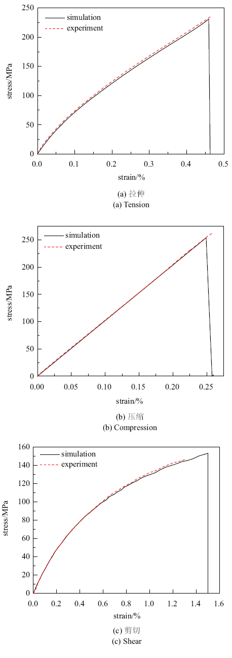
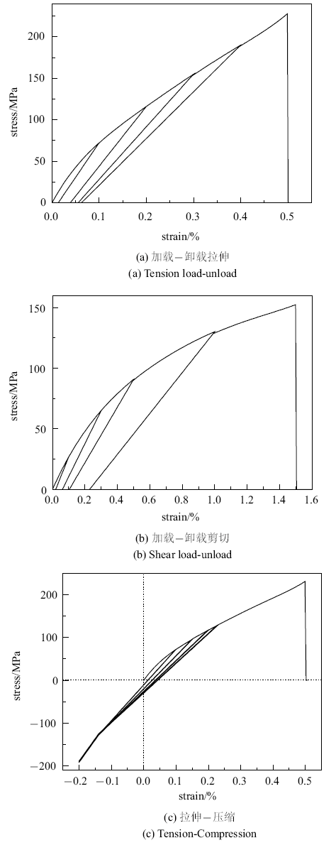
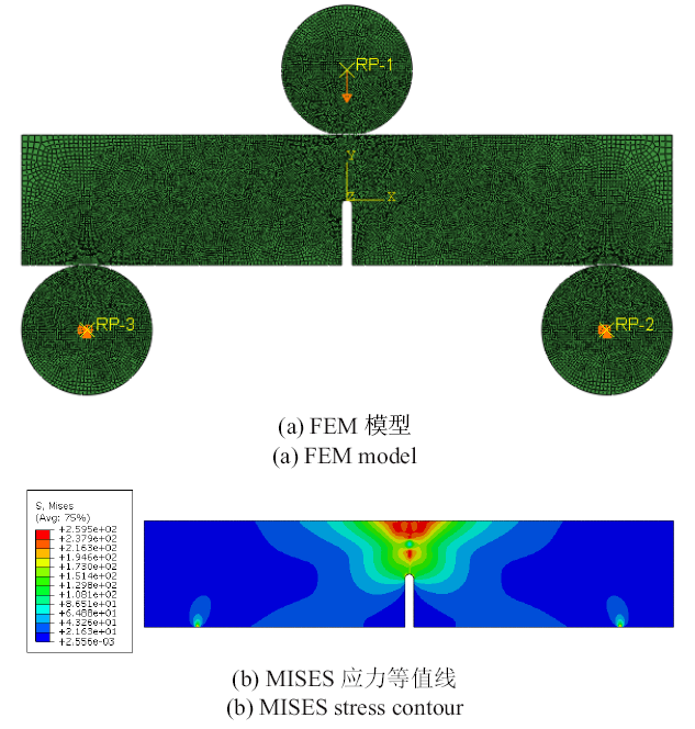
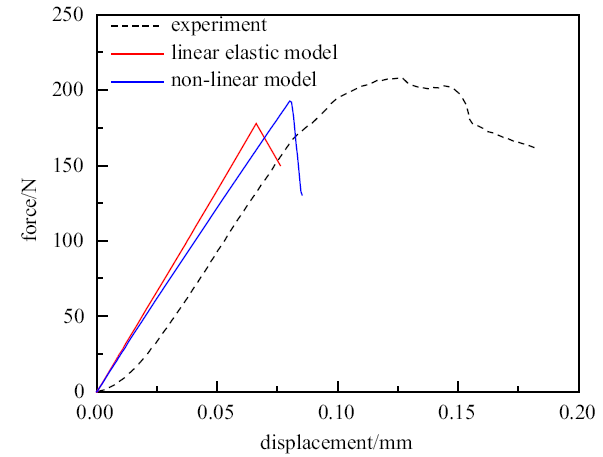
C/SiC composites have a series of advantages such as high specific strength, high specific modulus, excellent thermal stability, etc, being widely used in the aerospace field. Brittle fracture caused by crack propagation is one of its main failure forms. Therefore, the fracture performance analysis of the material has important guiding significance for the structural design and application of the material. Simple mechanical experiments and fracture experiments of stitched C/SiC composites are carried out, the mechanical response and fracture characteristics of the materials under different loads being studied in the paper. Based on simple mechanical experiments of stitched C/SiC composites, the macroscopic nonlinear damage constitutive equation is established, and the fracture behavior of stitched C/SiC composites with unilateral notched beam and double cantilever beam are simulated. The constitutive equation uses simple equations to describe the nonlinear stress-strain curve of the material under complex stress conditions, and considers the crack closure on the reverse loading process. Based on the commercial finite element software ABAQUS, the non-linear damage constitutive equations are realized by writing a UMAT subroutine. The validity of the established constitutive equation is verified by a single element. On this basis, the linear elastic damage constitutive model and the nonlinear damage constitutive model are used to simulate the fracture behavior of the stitched C/SiC composites with a single-side notched beam and a double cantilever beam, respectively. The force-displacement curves simulated by the nonlinear damage constitutive equation are more consistent with the test results, and the failure load predicted by the nonlinear damage constitutive are closer to the test failure load, which verifies the accuracy of the nonlinear damage constitutive equation established in this paper. The paper provides a reference for the study of the fracture behavior of C/SiC composites and provides a theoretical basis for the design and application of stitched C/SiC composites structures.
Cao Mingyue, Zhang Qi, Wu Jianguo, Ge Jingran, Liang Jun. STUDY ON NONLINEAR CONSTITUTIVE RELATIONSHIP AND FRACTURE BEHAVIOR OF STITCHED C/SiC COMPOSITES$^{\bf 1)}$. Chinese Journal of Theoretical and Applied Mechanics[J], 2020, 52(4): 1095-1105 DOI:10.6052/0459-1879-20-058
A SiC/SiC composite is a candidate material for a demonstration fusion power reactor (DEMO). Identifying the inherent anisotropy of composites is required to predict axial/off-axial mechanical properties for various failure modes. This study evaluated crack propagation behavior by the various modes to provide strength anisotropy maps and we discussed a method to analytically predict this trend. The strength anisotropy maps identified for various fabric orientations clearly indicate that the composites failed in the mixed modes. Specifically, due to the axial anisotropy, five individual mode strengths such as tensile/compressive strengths in the axial/transverse directions, respectively, as well as the in-plane shear strength, are identified to become essential input parameters. With the analytical criterion based on the Tsai-Wu model, the strength anisotropy could satisfactorily be described. (C) 2012 Elsevier B.V.
LiJ, JiaoG, WangBD, et al.
Damage characteristics and constitutive modeling of the 2D C/Si C composite: Part I-Experiment and analysis
Chinese Journal of Aeronautics, 2014,27(6):1586-1597
This paper reports an experimental investigation on the macroscopic mechanical behaviors and damage mechanisms of the plain-woven (2D) C/SiC composite under in-plane on-and off-axis loading conditions. Specimens with 15 degrees, 30 degrees, and 45 degrees off-axis angles were prepared and tested under monotonic and incremental cyclic tension and compression loads. The obtained results were compared with those of uniaxial tension, compression, and shear specimens. The relationships between the damage modes and the stress state were analyzed based on scanning electronic microscopy (SEM) observations and acoustic emission (AE) data. The test results reveal the remarkable axial anisotropy and unilateral behavior of the material. The off-axis tension test results show that the material is fiber-dominant and the evolution rate of damage and inelastic strain is accelerated under the corresponding combined biaxial tension and shear loads. Due to the damage impediment effect of compression stress, compression specimens show higher mechanical properties and lower damage evolution rates than tension specimens with the same off-axis angle. Under cyclic tension-compression loadings, both on-axis and off-axis specimens exhibit progressive damage deactivation behaviors in the compression range, but with different deactivation rates. (C) 2014 Production and hosting by Elsevier Ltd. on behalf of CSAA & BUAA.
DassiosKG, KostopoulosV, SteenM.
Intrinsic parameters in the fracture of carbon/carbon composites
Composites Science and Technology, 2005,65(6):883-897
The R-curve, bridging stress profile and the corresponding bridging law of C/C woven composites were calculated for two different specimen configurations: compact tension (CT) and double-edge-notch (DEN). Monotonic tensile loading as well as cyclic loading was performed on CT specimens and the R-curve was evaluated from the change of specimen compliance in the presence and absence of the bridging zone by quantifying the total damage in the material through an effective crack length approach. The bridging stresses and laws for the DEN specimens tested under monotonic tension were calculated directly through the elastic correction of the measured displacement. The comparison of the R-curves and bridging laws between the two configurations was performed after identification of a common damage extent measure, the local crack opening displacement. The rising part of the R-curve was found similar for the two configurations, with the mean initiation and plateau values being R0 ∼ 1.3 and R∞ ∼ 9.5 kJ/m2, respectively. In contrast, the bridging laws evaluated for the two configurations were in disagreement. It was concluded that the investigated material, although characterised as Class-III in the literature, exhibits crack growth and bridging, however of a Small rather of a large scale and that the calculated R-curve can serve as an intrinsic parameter that characterises the fracture behaviour of the material independently of configuration, and – thus – independently of dimensions and geometry.
XieD, SalviA, WaasA, et al.
Discrete cohesive zone model to simulate static fracture in carbon fiber composites
Journal of Composite Materials, 2005,40(22):2025-2046
In this investigation, a finite element formulation for Timoshenko beam element with only displacement degrees of freedom is first addressed for the laminated composite beams. The resulting continuous isoparametric quadrilateral element is simple to formulate and efficient through the convergence with coarse meshes along the crack tip. Afterwards, a finite element procedure is proposed for the simulation of mode I delamination growth in symmetric multidirectional double cantilever beam (DCB) specimens based on the fracture mechanics using the above-mentioned element. To take into account R-curve effects in DCB specimens, a variable strain energy release rate is utilized instead of constant initiation fracture toughness. The strain energy release rate is computed using virtual crack closure technique (VCCT) method. The results of the finite element simulation agree well with the experimental data available in the literature. It confirms that the proposed approach is reliable and feasible for modeling of mode I delamination growth in laminated composites with large-scale fiber bridging. (c) 2012 Elsevier B.V.
LiuPF, HouSJ, ChuJK, et al.
Finite element analysis of postbuckling and delamination of composite laminates using virtual crack closure technique
The two-dimensional and three-dimensional parametric finite element analysis (FEA) of composite flat laminates with two through-the-width delamination types: 0(4)/(+/-theta)(6)//0(4) and 0(4)//(+/-theta)(6)//0(4) (theta = 0 degrees, 45 degrees, and "//" denotes the delaminated interface) under compressive load are performed to explore the effects of multiple delaminations on the postbuckling properties. The virtual crack closure technique which is employed to calculate the energy release rate (ERR) for crack propagation is used to deal with the delamination growth. Three typical failure criteria: B-K law, Reeder law and Power law are comparatively studied for predicting the crack propagation. Effects of different mesh sizes and pre-existing crack length on the delamination growth and postbuckling properties of composite laminates are discussed. Interaction between the delamination growth mechanisms for multiple cracks for 0(4)//(+/-theta)(6)//0(4) composite laminates is also investigated. Numerical results using FEA are also compared with those by existing models and experiments. (C) 2010 Elsevier Ltd.
AymerichF, DoreF, PrioloP.
Prediction of impact-induced delamination in cross-ply composite laminates using cohesive interface elements
Composites Science and Technology, 2008,68(12):2383-2390
The paper investigates the potential of cohesive interface elements for damage prediction in laminates subjected to low-velocity impact. FE models with interface elements adopting a bilinear cohesive law were first calibrated and validated by simulation of standard fracture toughness tests and then employed to model the impact response of cross-ply graphite/epoxy laminated plates.
The developed model provided a correct simulation of the impact response of laminates in a wide range of energy values and successfully predicted size, shape and location of main damage mechanisms. The results of the analyses also pointed out the importance of employing a damage criterion capable of accounting for the constraining effect of out-of-plane compression on the initiation of the decohesion phase.
HarperPW, HallettSR.
A fatigue degradation law for cohesive interface elements-Development and application to composite materials
International Journal of Fatigue, 2010,32(11):1774-1787
A cohesive zone interface element degradation law is presented for analyzing delamination crack propagation under cyclic loading. Development of the law is based on a detailed study of the numerical cohesive zone and the extraction of strain energy release rate from this zone, enabling a direct link with experimental Paris Law data. The law is implemented using three-dimensional interface elements within the explicit finite element code LS-Dyna. Validation is presented by way of application to composite material fatigue fracture toughness tests; Double Cantilever Beam for Mode I, End Notch Flexure for mode II and Mixed Mode Bending for the mixed mode case. In all cases good agreement with experimental data available in the open literature and/or theoretical solutions was obtained.
Time-independent orthotropic enrichment functions are introduced for dynamic propagation analysis of moving cracks in composites by the extended finite element method (XFEM). The proposed enrichment functions are derived from the analytical solutions for a moving/propagating crack in orthotropic media, and can be considered as a new extension to the available XFEM techniques for dynamic analysis of stationary and moving cracks in orthotropic materials. They are included within the framework of partition of unity and XFEM to enhance the accuracy of basic FEM solution near a moving crack tip in orthotropic media. The method allows for analysis of the whole crack propagation pattern on an unaltered finite element mesh, which is independently defined from the existence of any predefined crack or its propagation path. A combination of dynamic crack initiation toughness and crack orientation along the maximum circumferential stress is used to design a relatively simple and efficient formulation. Dynamic stress intensity factors (DSIFs) are evaluated by means of the domain separation integral method and the dynamic energy release rate. The time dependent XFEM equations are constructed by discretizing the standard weak formulation of the governing elastodynamics equation. They are solved by the unconditionally stable Newmark time integration scheme. A number of benchmark and test problems are simulated and the results are compared with the available reference results to illustrate the accuracy and efficiency of the proposed scheme. (C) 2011 Elsevier Ltd.
BaydounM, Fries TP.
Crack propagation criteria in three dimensions using the XFEM and an explicit-implicit crack description
International Journal of Fracture, 2012,178(1-2):51-70
This paper studies propagation criteria in three-dimensional fracture mechanics within the extended finite element framework (XFEM). The crack in this paper is described by a hybrid explicit-implicit approach as proposed in Fries and Baydoun (Int J Numer Methods Eng, 2011). In this approach, the crack update is realized based on an explicit crack surface mesh which allows an investigation of different propagation criteria. In contrast, for the computation of the displacements, stresses and strains by means of the XFEM, an implicit description by level set functions is employed. The maximum circumferential stress criterion, the maximum strain energy release rate criterion, the minimal strain energy density criterion and the material forces criterion are realized. The propagation paths from different criteria are studied and compared for asymmetric bending, torsion, and combined bending and torsion test cases. It is found that the maximum strain energy release rate and maximum circumferential stress criterion show the most favorable results.
ChenC, CaiHY, LiJJ, et al.
One-dimensional extended FEM based approach for predicting the tensile behavior of SHCC-FRP composites
In this work, a macroscopic non-linear constitutive model accounting for damage, inelastic strain and unilateral behavior is proposed for the 2D plain-woven C/SiC composite. A set of scalar damage variables and a new thermodynamic potential expression are introduced in the framework of continuum damage mechanics. In the deduced constitutive equations, the material's progressive damage deactivation behavior during the compression loading is described by a continuous function, and different deactivation rates under uniaxial and biaxial compression loadings are also considered. In damage evolution laws, the coupling effect among the damage modes and impediment effect of compression stress on the development of shear damage in different plane stress states are taken into account. Besides, the general plasticity theory is applied to describing the evolution of inelastic strain in tension and/or shear stress state. The Tsai-Wu failure criterion is adopted for strength analysis. Additionally, the material model is implemented as a user-defined material subroutine (UMAT) and linked to the ABAQUS finite element software, and its performance is demonstrated through several numerical examples.
WeiL, ZhuW, YuZ, et al.
A new three-dimensional progressive damage model for fiber-reinforced polymer laminates and its applications to large open-hole panels
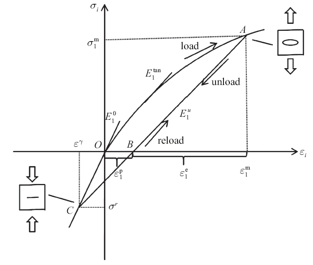
Based on the fundamental mechanical tests of 2D woven C/SiC composite material, a macroscopic orthotropic non-linear damage constitutive model was established. In this model, the detectable strains were chosen as variables, and functions in simple form were used to demonstrate the stress-strain relationship of the material under damage evolution caused by uniaxial tension and shear loads, and besides the rule of stiffness change in unloading state respectively. Meanwhile, the unilateral effect and damage-deactivation behavior were also considered. The constitutive model was implemented into UMAT in ABAQUS finite element software, and it could describe the material’s non-linear and linear property of stress-strain relationship in loading and unloading state respectively, and also its load history. Through modeling the open hole plates in tension, strain distribution besides the hole agrees well with the experiment result, which proves the availability of the proposed constitutive model.
( LiJun, JiaoGuiqiong, WangBo, et al.
Nonlinear damage constitutive model of 2D braided C/SiC composites and its application
Acta Materiae Compositae Sinica, 2013,30(1):165-171 (in Chinese))
Based on the fundamental mechanical tests of 2D woven C/SiC composite material, a macroscopic orthotropic non-linear damage constitutive model was established. In this model, the detectable strains were chosen as variables, and functions in simple form were used to demonstrate the stress-strain relationship of the material under damage evolution caused by uniaxial tension and shear loads, and besides the rule of stiffness change in unloading state respectively. Meanwhile, the unilateral effect and damage-deactivation behavior were also considered. The constitutive model was implemented into UMAT in ABAQUS finite element software, and it could describe the material’s non-linear and linear property of stress-strain relationship in loading and unloading state respectively, and also its load history. Through modeling the open hole plates in tension, strain distribution besides the hole agrees well with the experiment result, which proves the availability of the proposed constitutive model.
MccarthyCT, O'HigginsRM, FrizzellRM.
A cubic spline implementation of non-linear shear behaviour in three-dimensional progressive damage models for composite laminates
An experimental study was carried out to characterise the constitutive response of carbon fibre-reinforced epoxy laminates. While maintaining essentially linear behaviour in the fibre and transverse directions, this material displays significant non-linear shear stress–strain behaviour to rupture. It is shown that the well known Hahn-Tsai non-linear shear model does not provide an acceptable fit for the strain range examined and so a novel approach was derived where a cubic spline interpolation method was used to capture the non-linear shear behaviour. The well known ply discount model, based on Hashin’s failure criteria, was also used to predict fibre and transverse matrix damage in the laminates. The spline approach is coupled with maximum strain failure criteria to predict the response in the in-plane and out-of-plane shear directions. The material Jacobian matrix is fully defined, thus allowing a full implicit material model to be implemented. Hence, the model is suitable for both implicit and explicit finite element codes. It is shown that the model accurately predicts the response of the material for load cases in which shear stresses dominate. The performance of the model is demonstrated by considering a number of laminate configurations and failure of an open-hole tension specimen.
Elias NEliopoulos, Theodore PPhilippidis.
A progressive damage simulation algorithm for GFRP composites under cyclic loading. Part I: Material constitutive model


