0 引言
迄今为止,小变形情形下的柔性多体系统动力学得到了深入研究,取得了丰富的理论成果. Likins [1]提出了 混合 坐标 方法(hybrid-coordinate formulation),即对柔性体建立浮动坐标系,将柔性体的运动分解为浮动坐标系的牵连大范围运动和其相对浮动坐标系的变形运动的叠加,并将描述浮动坐标系大范围刚体运动的坐标与柔性体变形运动的节点坐标(或模态坐标)作为柔性体的广义坐标,在此基础上建立系统的动力学方程(由于这种方法需要建立柔性体浮动坐标系,所以该方法也称为浮动坐标系法(floating frame of reference,FFR)). 1987年,Kane等[2]在研究运动刚体上柔性梁的动力学时发现传统的混合坐标方法由于忽略了应变-位移关系式中的二次项,从而导致在处理高速旋转的悬臂梁动力学问题时失效,并提出了"动力刚化"的概念.国内外学者对动力刚化问题展开了研究,提出了几何变形约束方法[3]﹑几何非线性法[4]﹑子结构法[5]﹑初应力法[6],并由此形成了更加精确考虑刚柔耦合效应的一次近似耦合模型[7, 8, 9, 10, 11, 12, 13, 14, 15, 16].
随着新材料和新技术的不断出现,含大变形构件的刚柔耦合系统愈来愈被广泛应用于机器人、航空、航天、机械、军事等领域.例如现代机器人、风力发电机叶片、直升机旋翼以及数十米长的太空机械臂等都是一些由刚体和柔性体组成的刚柔耦合系统.在运动中,系统中柔性附件都可能经历大的弹性变形.传统的基于小变形假设的刚柔耦合动力学理论已不能完全解决这类问题,需要考虑柔性附件的大变形效应.为了处理柔性体大变形问题,Shabana[17]提出了绝对节点坐标法(absolute nodal coordinate formulation,ANCF).该方法的特点是直接选取柔性体各单元节点相对惯性基的位置和斜率作为广义坐标,不需要将柔性体的运动分解为大范围刚性运动和弹性变形,所建立的动力学方程的广义质量阵为常值阵. Berzeri和Shabana[18]基于绝对节点坐标法,提出了平面梁的3种几何非线性动力学模型,研究了各种模型对大变形问题的适用性,并用绝对节点坐标法研究了动力刚化问题[19].Omar和Shabana [20]进一步考虑剪切效应,建立了二维梁的有限元模型. Shabana 和 Mikkola [21]基于绝对节点坐标法对大变形折梁的建模方法进行研究,通过转换矩阵来实现折梁的斜率不连续问题.由于平面梁单元每个节点坐标包括2个绝对位置和4个绝对位置梯度,该方法需要求解的自由度特别多,而且弹性力高度非线性,所以计算效率较低.为了提高计算效率,Yoo等[22]用混合坐标法建立了折梁系统的动力学模型.但由于在公式推导过程中忽略了变形的高次项,该方法仅适用于小变形折梁的仿真计算,不适用于大变形问题.绝对节点坐标法能很好地处理柔性体的大变形问题,但其广义坐标中仅包含了节点的绝对位置坐标及其梯度,没有直接区分刚体的运动变量与节点的弹性变形,即使是小变形问题也要按照大变形的方法处理,计算效率较低.
对于柔性体大变形动力学建模除了采用绝对节点坐标法外[15, 16, 17, 18, 19, 23, 24, 31],也可以在浮动坐标系法框架内进行研究.文献[25, 26, 27, 28, 29, 30]提出了考虑非线性耦合变形量高阶项的高次耦合动力学模型,研究表明当柔性梁变形较大或者变形速度较大时一次近似耦合模型将出现计算发散的情况,而高次耦合模型的计算结果则依然收敛.
然而深入研究发现,文献[25, 26, 27, 28, 29, 30]在计算柔性梁变形能时,横向弯曲变形能部分实际上采用的是小变形假设下的能量公式,忽略了大变形效应. 本文在上述模型的基础上进一步考虑了柔性梁的纵向变形对横向弯曲变形能的影响,在浮动坐标系下使用柔性梁参数方程的精确曲率公式来计算柔性梁的弯曲变形能,并由此建立更加精确的刚柔耦合动力学模型,该模型能更好地处理柔性梁大位移运动下的大变形问题.
1 刚柔耦合动力学方程
1.1 物理模型
本文研究对象为平面细长Euler-Bernoulli梁系统,不考虑剪切变形和横截面的转动惯量. 假设梁的材料分布均匀且各向同性,认为变形时梁的横截面仍然保持为平面且与中轴线垂直.
考虑图1所示刚柔耦合系统,中心刚体在平面内做定轴转动,其上以悬臂方式连接一柔性梁. 通过刚体转动轴$O$建立一个惯性坐标系$O$-$XY$,在柔性梁上建立浮动坐标系$o$-$xy$,其中$o$为柔性梁与刚体连接处,$x$轴沿未变形时梁的轴线,$ox$轴与$OX$ 轴夹角为 $\theta $. 刚体绕转动轴$O$的转动惯量为$J_{oh}$,半径为$a$,柔性梁的长度为$L$,密度为 $\rho $,横截面积为$S$,截面惯性矩为$I$.
1.2 系统动力学方程
对于柔性梁上的任意一点$P_{0}(x)$在变形后的矢径(如图1)为
|
\[\text{r=(a+x +}{{\text{u}}_{\text{1}}}\text{)}{{\text{e}}_{\text{x}}}\text{+}{{\text{w}}_{\text{2}}}{{\text{e}}_{\text{y}}}\]
|
(1) |
其中,$w_{2}(x,t)$为沿$y$轴横向弯曲变形量,$u_{1}(x,t)$为沿$x$轴纵向变形量,$u_{1}(x,t)=w_{1}(x,t)+ w_{c}(x,t)$,式中$w_{1}(x,t)$为轴线轴向拉压变形量,$w_{c}(x,t)$是横向弯曲变形引起的梁的纵向缩短量,称为非线性耦合变形量. $w_{c}(x,t)$表示为
|
\[{{w}_{\text{c}}}(x,t)=-\frac{1}{2}\int_{0}^{x}{(}\frac{\partial {{w}_{2}}}{\partial \xi }{{)}^{2}}d\xi \]
|
(2) |
将式(1)对时间$t$进行求导,得到该点的速度为
|
\[\begin{align}
& \dot{r}=({{{\dot{w}}}_{1}}+{{{\dot{w}}}_{c}}-{{w}_{2}}\dot{\theta }){{e}_{x}}+ \\
& [(a+x+{{w}_{1}}+{{w}_{c}})\dot{\theta }+{{{\dot{w}}}_{2}}]{{e}_{y}} \\
\end{align}\]
|
(3) |
于是,系统的动能表示为
|
\[T=\frac{1}{2}{{J}_{oh}}{{\dot{\theta }}^{2}}+\frac{1}{2}\int_{0}^{L}{\rho S{{{\dot{r}}}^{T}}\dot{r}}dx\]
|
(4) |
系统的势能包括重力势能和弹性变形能,表达式为
|
\[V={{V}_{\text{G}}}+{{V}_{\text{E}}}\]
|
(5) |
不考虑重力势能的影响($V_{\rm G} = 0$),系统的总势能只有弹性变形能,包括轴向拉压变形能$V_l $和横向弯曲变形能$V_\kappa $. 在小变形假设下,可表示为
|
\[\left. \begin{align}
& {{V}_{\text{G}}}=0 \\
& V={{V}_{\text{E}}}={{V}_{l}}+{{V}_{\kappa }} \\
\end{align} \right\}\]
|
(6) |
|
\[{{V}_{l}}=\frac{1}{2}\int_{0}^{L}{ES{{\left( \frac{\partial {{w}_{1}}(x,t)}{\partial x} \right)}^{2}}}dx\]
|
(7) |
|
\[{{V}_{\kappa }}=\ \frac{1}{2}\int_{0}^{L}{EI{{\left( \frac{{{\partial }^{2}}{{w}_{2}}(x,t)}{\partial {{x}^{2}}} \right)}^{2}}}dx\]
|
(8) |
但是,在大变形情况时,柔性梁的弯曲变形能就不能简单地表示为式(8),而应该用柔性梁的精确曲率公式来计算. 柔性梁任意一点$P_{0}(x)$在浮动坐标系$o$-$xy$平面内的参数方程为
|
\[\left. \begin{array}{*{35}{l}}
\phi (x,t)=x+{{w}_{1}}(x,t)+{{w}_{c}}(x,t) \\
\psi (x,t)={{w}_{2}}(x,t) \\
\end{array} \right\}\]
|
(9) |
由曲率与矢径导数之间关系得
|
\[\kappa (x)=\frac{\left| \frac{\partial \varphi (x,t)}{\partial x}\frac{{{\partial }^{2}}\psi (x,t)}{\partial {{x}^{2}}}-\frac{{{\partial }^{2}}\varphi (x,t)}{\partial {{x}^{2}}}\frac{\partial \psi (x,t)}{\partial x} \right|}{{{\left[ {{(\frac{\partial \varphi (x,t)}{\partial x})}^{2}}+{{(\frac{\partial \psi (x,t)}{\partial x})}^{2}} \right]}^{3/2}}}\]
|
(10) |
由此可得柔性梁的弯曲变形能为
|
\[\begin{align}
& {{V}_{\kappa }}=\frac{1}{2}\int_{0}^{L}{EI{{\kappa }^{2}}(x)}dx=\frac{1}{2}\int_{0}^{L}{EI}\cdot \\
& \frac{{{\left| \frac{\partial \varphi (x,t)}{\partial x}\frac{{{\partial }^{2}}\psi (x,t)}{\partial {{x}^{2}}}-\frac{{{\partial }^{2}}\varphi (x,t)}{\partial {{x}^{2}}}\frac{\partial \psi (x,t)}{\partial x} \right|}^{2}}}{{{\left[ {{(\frac{\partial \varphi (x,t)}{\partial x})}^{2}}+{{(\frac{\partial \psi (x,t)}{\partial x})}^{2}} \right]}^{3}}}dx \\
\end{align}\]
|
(11) |
|
\[\begin{align}
& \frac{\partial \varphi (x,t)}{\partial x}=1+\frac{\partial {{w}_{1}}(x,t)}{\partial x}+\frac{\partial {{w}_{c}}(x,t)}{\partial x}= \\
& 1+\frac{\partial {{w}_{1}}(x,t)}{\partial x}-\frac{1}{2}{{(\frac{\partial {{w}_{2}}(x,t)}{\partial x})}^{2}} \\
\end{align}\]
|
(12) |
|
\[\frac{\partial \psi (x,t)}{\partial x}=\frac{\partial {{w}_{2}}(x,t)}{\partial x}\]
|
(13) |
式(12)和式(13)继续对$x$求偏导,舍去$\dfrac{\partial ^{2}w_1(x,t)}{\partial x^{2}}$,则
|
\[\frac{{{\partial }^{2}}\psi (x,t)}{\partial {{x}^{2}}}=\frac{{{\partial }^{2}}{{w}_{2}}(x,t)}{\partial {{x}^{2}}}\]
|
(14) |
|
\[\frac{{{\partial }^{2}}\phi (x,t)}{\partial {{x}^{2}}}=-\frac{\partial {{w}_{2}}(x,t)}{\partial x}\frac{{{\partial }^{2}}{{w}_{2}}(x,t)}{\partial {{x}^{2}}}\]
|
(15) |
|
\[\begin{align}
& {{(\frac{\partial \phi (x,t)}{\partial x})}^{2}}+{{(\frac{\partial \psi (x,t)}{\partial x})}^{2}}= \\
& 1+2\frac{\partial {{w}_{1}}(x,t)}{\partial x}-\frac{\partial {{w}_{1}}(x,t)}{\partial x}{{(\frac{\partial {{w}_{2}}(x,t)}{\partial x})}^{2}}+ \\
& {{(\frac{\partial {{w}_{1}}(x,t)}{\partial x})}^{2}}+\frac{1}{4}{{(\frac{\partial {{w}_{2}}(x,t)}{\partial x})}^{4}} \\
\end{align}\]
|
(16) |
舍去$\dfrac{\partial w_2 (x,t)}{\partial x}$的4次项(以后方程中 $\dfrac{\partial w_2(x,t)}{\partial x}$的4次项都舍去),$\dfrac{\partial w_{1} (x,t)}{\partial x}$的2次项(以后方程中$\dfrac{\partial w_{1} (x,t)}{\partial x}$的2次项都舍去)和$\dfrac{\partial w_1 (x,t)}{\partial x}\Big(\dfrac{\partial w_2 (x,t)}{\partial x}\Big)^2$项,可得
|
\[{{(\frac{\partial \phi (x,t)}{\partial x})}^{2}}+{{(\frac{\partial \psi (x,t)}{\partial x})}^{2}}=1+2\frac{\partial {{w}_{1}}(x,t)}{\partial x}\]
|
(17) |
|
\[\begin{align}
& \frac{\partial \phi (x,t)}{\partial x}\frac{{{\partial }^{2}}\psi (x,t)}{\partial {{x}^{2}}}-\frac{{{\partial }^{2}}\phi (x,t)}{\partial {{x}^{2}}}\frac{\partial \psi (x,t)}{\partial x}= \\
& \frac{{{\partial }^{2}}{{w}_{2}}(x,t)}{\partial {{x}^{2}}}+\frac{1}{2}{{(\frac{\partial {{w}_{2}}(x,t)}{\partial x})}^{2}}\frac{{{\partial }^{2}}{{w}_{2}}(x,t)}{\partial {{x}^{2}}} \\
\end{align}\]
|
(18) |
|
\[\begin{align}
& {{V}_{\kappa }}=\frac{1}{2}\int_{0}^{L}{EI{{\kappa }^{2}}\left( x \right)}dx= \\
& \frac{1}{2}\int_{0}^{L}{EI\frac{{{\left| \frac{{{\partial }^{2}}{{w}_{2}}(x,t)}{\partial {{x}^{2}}}+\frac{1}{2}{{(\frac{\partial {{w}_{2}}(x,t)}{\partial x})}^{2}}\frac{{{\partial }^{2}}{{w}_{2}}(x,t)}{\partial {{x}^{2}}} \right|}^{2}}}{{{\left[ 1+2\frac{\partial {{w}_{1}}(x,t)}{\partial x} \right]}^{3}}}}dx \\
\end{align}\]
|
(19) |
对$\left( { 1 + 2\dfrac{\partial w_1 (x,t)}{\partial x}} \right)^{-3}$泰勒展开
|
\[\begin{align}
& {{\left( 1+2\frac{\partial {{w}_{1}}(x,t)}{\partial x} \right)}^{-3}}=1-6\frac{\partial {{w}_{1}}(x,t)}{\partial x}+ \\
& 12{{(\frac{\partial {{w}_{1}}(x,t)}{\partial x})}^{2}}+\cdots \\
\end{align}\]
|
(20) |
将式(20)中的二次项及以上项舍去,并代入式(19) 可得
|
\[\begin{align}
& {{V}_{\kappa }}=\frac{1}{2}\int_{0}^{L}{E}I\{[1+\frac{\partial {{w}_{1}}(x,t)}{\partial x}+ \\
& \frac{1}{2}{{(\frac{\partial {{w}_{2}}(x,t)}{\partial x})}^{2}}]\frac{{{\partial }^{2}}{{w}_{2}}(x,t)}{\partial {{x}^{2}}}{{\}}^{2}}\cdot \\
& (1-6\frac{\partial {{w}_{1}}(x,t)}{\partial x})\text{d}x= \\
& \frac{1}{2}\int_{0}^{L}{E}I{{(\frac{{{\partial }^{2}}{{w}_{2}}(x,t)}{\partial {{x}^{2}}})}^{2}}dx+ \\
& \underline{\frac{1}{2}\int_{0}^{L}{E}I{{(\frac{\partial {{w}_{2}}(x,t)}{\partial x})}^{2}}{{(\frac{{{\partial }^{2}}{{w}_{2}}(x,t)}{\partial {{x}^{2}}})}^{2}}dx}- \\
& \underline{\underline{2\int_{0}^{L}{EI\frac{\partial {{w}_{1}}(x,t)}{\partial x}{{(\frac{{{\partial }^{2}}{{w}_{2}}(x,t)}{\partial {{x}^{2}}})}^{2}}}dx}} \\
\end{align}\]
|
(21) |
式(21)中下划线项为纵向变形对横向弯曲变形能的贡献项,是由于计入纵向变形对曲率的影响,即曲率纵向变形效应而产生的,具体就是单划线项由式(9)中$w_c (x,t)$而产生,双划线项由式(9)中$w_1 (x,t)$而产生. 若去掉所有下划线项,就退化为传统的小变形假设下柔性梁的弯曲变形能表达式(8).
采用假设模态法描述柔性梁的变形,轴向拉压变形量$w_{1}$和横向变形量$w_{2}$表示为
|
\[\left. \begin{align}
& {{w}_{1}}(x,t)={{\Phi }_{x}}(x)A(t) \\
& {{w}_{2}}(x,t)={{\Phi }_{y}}(x)B(t) \\
\end{align} \right\}\]
|
(22) |
式中,${\Phi }_x (x) \in { R}^{1\times N}$和${\Phi }_y (x) \in { R}^{1\times N}$分别为梁的轴向振动和横向振动的模态函数的行矢量,${ A} (t)\in { R}^{N\times 1}$和${ B} (t) \in{ R}^{N\times 1}$分别为轴向振动和横向振动的模态坐标列矢量,则有
|
\[{{w}_{\text{c}}}=-\frac{1}{2}{{B}^{\text{T}}}H(x)B\]
|
(23) |
式中,${ H}(x) \in { R}^{N\times N}$为耦合形函数,其表达式为
|
\[H(x)=\int_{0}^{x}{{{\Phi }^{\prime }}_{y}^{\text{T}}}(\xi ){{{\Phi }'}_{y}}(\xi )d\xi \]
|
(24) |
$\Phi '_y (x)$表示${\Phi } _y (x)$对$x$求一次导,取广义坐标$q = \left( {\theta ,{ A}^{\rm T},{ B}^{\rm T}}\right)^ {\rm T}$,将式(4) $\sim$式(7),式(21)代入第二类拉格朗日方程,即可得到系统的动力学方程
其中,${ M}$为广义质量阵,${ Q}$为广义力阵.
广义质量阵${ M}$,广义力阵${ Q}$可分别表示为
|
\[\left. \begin{align}
& M=\left[ \begin{matrix}
{{M}_{11}} & {{M}_{12}} & {{M}_{13}} \\
{{M}_{21}} & {{M}_{22}} & {{M}_{23}} \\
{{M}_{31}} & {{M}_{32}} & {{M}_{33}} \\
\end{matrix} \right] \\
& Q=\left[ \begin{matrix}
{{Q}_{\theta }} \\
{{Q}_{A}} \\
{{Q}_{B}} \\
\end{matrix} \right]+\left[ \begin{matrix}
\tau \\
\mathbf{0} \\
\mathbf{0} \\
\end{matrix} \right] \\
\end{align} \right\}\]
|
(26) |
其中
|
\[\begin{align}
& {{M}_{11}}={{J}_{oh}}+{{J}_{ob}}+2{{S}_{x}}A+{{A}^{\text{T}}}{{M}_{x}}A+{{B}^{\text{T}}}{{M}_{y}}B- \\
& \underline{{{B}^{\text{T}}}CB}+\underline{\underline{\frac{1}{4}\int_{0}^{L}{\rho S({{B}^{\text{T}}}HB{{B}^{\text{T}}}HB)}dx}}- \\
& \underline{\underline{\int_{0}^{L}{\rho S({{A}^{\text{T}}}\Phi _{x}^{\text{T}}{{B}^{\text{T}}}HB)}dx}} \\
\end{align}\]
|
(27) |
|
\[{{\text{M}}_{\text{22}}}\text{ = }{{\text{M}}_{\text{x}}}\]
|
(28) |
|
\[{{M}_{33}}={{M}_{y}}+\underline{\underline{\int_{o}^{L}{\rho S(HB{{B}^{\text{T}}}H)}dx}}\]
|
(29) |
|
\[{{M}_{21}}=M_{12}^{\text{T}}=-{{M}_{xy}}B\]
|
(30) |
|
\[\begin{align}
& {{M}_{31}}=M_{13}^{\text{T}}=S_{y}^{\text{T}}+M_{xy}^{\text{T}}A+ \\
& \underline{\underline{\int_{0}^{L}{\rho }S(HB{{\Phi }_{y}}B-\frac{1}{2}\Phi _{y}^{\text{T}}{{B}^{\text{T}}}HB)dx}} \\
\end{align}\]
|
(31) |
|
\[{{M}_{32}}=M_{23}^{\text{T}}=\underline{\underline{-\int_{0}^{L}{\rho S(HB{{\Phi }_{x}}})dx}}\]
|
(32) |
|
\[\begin{align}
& {{Q}_{\theta }}=-2\dot{\theta }({{S}_{x}}\dot{A}+{{A}^{\text{T}}}{{M}_{x}}\dot{A}+{{B}^{\text{T}}}{{M}_{y}}\dot{B}-\underline{{{B}^{\text{T}}}C\dot{B}})- \\
& \underline{\underline{\int_{0}^{L}{\rho S({{B}^{\text{T}}}\Phi _{y}^{\text{T}}{{{\dot{B}}}^{\text{T}}}H\dot{B})}dx}}+ \\
& \underline{\underline{\dot{\theta }\int_{0}^{L}{\rho }S({{{\dot{A}}}^{\text{T}}}\Phi _{x}^{\text{T}}{{B}^{\text{T}}}HB+2{{A}^{\text{T}}}\Phi _{x}^{\text{T}}{{B}^{\text{T}}}H\dot{B}}}- \\
& \underline{\underline{{{B}^{\text{T}}}HB{{B}^{\text{T}}}H\dot{B})dx}} \\
\end{align}\]
|
(33) |
|
\[\begin{align}
& {{Q}_{A}}={{{\dot{\theta }}}^{2}}(S_{x}^{\text{T}}+{{M}_{x}}A)+2\dot{\theta }{{M}_{xy}}\dot{B}-{{K}_{1}}A- \\
& \underline{\underline{\frac{1}{2}{{{\dot{\theta }}}^{2}}\int_{0}^{L}{\rho S(\Phi _{x}^{\text{T}}{{B}^{\text{T}}}HB})dx}}+ \\
& \underline{\underline{\int_{0}^{L}{\rho }S(\Phi _{x}^{\text{T}}{{{\dot{B}}}^{\text{T}}}H\dot{B})dx}}+ \\
& \underline{\underline{\underline{\underline{2\int_{0}^{L}{E}I\Phi {{'}_{x}}^{T}{{B}^{T}}{{\Phi }_{y}}''(x){{\Phi }_{y}}''Bdx}}}} \\
\end{align}\]
|
(34) |
|
\[\begin{align}
& {{Q}_{B}}={{{\dot{\theta }}}^{2}}({{M}_{y}}\underline{-C})B-2\dot{\theta }M_{xy}^{\text{T}}\dot{A}-{{K}_{2}}B+ \\
& \underline{\underline{{{{\dot{\theta }}}^{2}}\int_{0}^{L}{\rho }S(\frac{1}{2}HB{{B}^{\text{T}}}HB-HB{{\Phi }_{x}}A)dx}}- \\
& \underline{\underline{2\dot{\theta }\int_{0}^{L}{\rho S}(HB{{\Phi }_{y}}\dot{B}-\Phi _{y}^{\text{T}}{{B}^{\text{T}}}H\dot{B})dx}}- \\
& \underline{\underline{\int_{0}^{L}{\rho S}(HB{{{\dot{B}}}^{\text{T}}}H\dot{B})dx}}- \\
& \underline{\underline{\underline{\mathop{\int }_{0}^{L}EI\Phi '{{'}_{y}}^{T}{{\Phi }_{y}}''B{{B}^{T}}\Phi {{'}_{y}}^{T}{{\Phi }_{y}}'Bdx-}}} \\
& \underline{\underline{\underline{\int_{0}^{L}{E}I{{B}^{T}}\Phi '{{'}_{y}}^{T}{{\Phi }_{y}}''B\Phi {{'}_{y}}^{T}{{\Phi }_{y}}'Bdx+}}} \\
& \underline{\underline{\underline{\underline{4\int_{0}^{L}{E}I{{\Phi }_{x}}'A\Phi '{{'}_{y}}^{T}{{\Phi }_{y}}''Bdx}}}} \\
\end{align}\]
|
(35) |
式中,${ \Phi }_i (i = x,y)$表示${ \Phi }_i (x) (i = x,y)$,${ \Phi }'_i
(i = x,y)$表示${ \Phi }_i (x) (i = x,y)$对$x$求一次导,${ \Phi }"_i (i = x,y)$表示${
\Phi }_i (x) (i = x,y)$对$x$求两次导数.
式(25)即为本文所提出的考虑曲率纵向变形效应的刚柔耦合动力学模型(简称曲率纵向变形效应模型).式(34)和式(35)中,三划线项和四划线项分别由式(21)中单划线项和双划线项产生.若去掉三、四划线项,则方程退化为作大位移运动柔性梁的高次刚柔耦合动力学模型(高次耦合模型)[27];再去掉双划线项,则变为大位移运动柔性梁的一次近似刚柔耦合动力学模型(一次近似耦合模型)[8],英文名称是 first-order approximate coupled (FOAC)model;去掉所有划线项,式(25)就退化为大位移运动柔性梁的零次近似刚柔耦合动力学模型(传统零次耦合模型),英文名称是zeroth-order approximate coupled (ZOAC) model;若再忽略大位移运动,则变为结构动力学模型.因此,式(25)实际上包含了5个层次的动力学模型. 式中${ J}_{ob} $,${ S }_x $,${ S }_y $,${ M}_x$,${ M}_y $,${ M}_{xy} $,${ C}$,${ K}_1 $,${ K}_2 $为相关的常系数矩阵.
|
\[{{J}_{ob}}=\int_{0}^{L}{\rho S{{(a+x)}^{2}}}dx\]
|
(36) |
|
\[{{S}_{x}}=\int_{0}^{L}{\rho }S(a+x){{\Phi }_{x}}(x)dx\]
|
(37) |
|
\[{{S}_{y}}=\int_{0}^{L}{\rho }S(a+x){{\Phi }_{y}}(x)dx\]
|
(38) |
|
\[{{M}_{x}}=\int_{0}^{L}{\rho S}\Phi _{x}^{\text{T}}(x){{\Phi }_{x}}(x)dx\]
|
(39) |
|
\[{{M}_{y}}=\int_{0}^{L}{\rho S}\Phi _{y}^{\text{T}}(x){{\Phi }_{y}}(x)dx\]
|
(40) |
|
\[{{M}_{xy}}=\int_{0}^{L}{\rho }S\Phi _{x}^{\text{T}}(x){{\Phi }_{y}}(x)dx\]
|
(41) |
|
\[C=\int_{0}^{L}{\rho }S(a+x)H(x)dx\]
|
(42) |
|
\[{{K}_{1}}=\int_{0}^{L}{E}S\Phi {{'}_{x}}^{T}(x)\Phi {{'}_{x}}(x)dx\]
|
(43) |
|
\[{{K}_{2}}=\int_{0}^{L}{E}I\Phi \text{ }\!\!'\!\!\text{ }\!\!'\!\!\text{ }_{y}^{\text{T}}(x)\Phi \text{ }\!\!'\!\!\text{ }{{\text{ }\!\!'\!\!\text{ }}_{y}}(x)dx\]
|
(44) |
2 算例
2.1 做大范围旋转运动刚体-悬臂梁系统
假设作用在中心刚体上的外力矩为
|
\[\tau (t)=\left\{ \begin{array}{*{35}{l}}
{{\tau }_{0}}\sin (\frac{2\pi }{T}t), & 0\le t\le T \\
0, & t>T \\
\end{array} \right.\]
|
(45) |
其中,$T = 2$ s.
系统参数采用文献[27]的数据,如表1所示.
表1(Table 1)

表1 刚体-悬臂梁参数Table 1 Data of hub-beam
| Property | Symbol | Value |
| length of the beam | $L$ | 5 m |
| section area of the beam | $S$ | 4×10$^{-4}$ m$^{2}$ |
| section moment of inertia | $I$ | 1.33×10$^{-8 }$ m$^{4}$ |
| density of the beam | $\rho $ | 2 766.7 kg/m$^{3}$ |
| elastic modulus of the beam | $E$ | 68.952 GPa |
| radius of the hub | $a$ | 1 m |
| rotary inertia of the hub | $J_{oh}$ | 5 kg$\cdot$m$^{2}$ |
|
表1 刚体-悬臂梁参数
Table 1 Data of hub-beam |
图2(a)为当驱动力矩$\tau _0 = 50
$ Nm时,曲率纵向变形效应模型,高次耦合模型和一次近似耦合模型,这3种模型下的柔性梁末端横向变形时程曲线.从图中可以发现,在该驱动力矩下,柔性梁的末端最大位移为0.37 m,这对于5 m长的柔性梁来说是小变形,此时3种模型得到的结果几乎完全吻合. 同时也说明一次近似耦合模型在小变形情况下是适用的. 图2(b)为当驱动力矩$\tau _0 = 150$ Nm时,这3种耦合模型下的柔性梁末端横向变形时程曲线.在该驱动力矩下,曲率纵向变形效应模型和高次模型吻合得比较好,而一次近似耦合模型开始出现误差.此时最大变形已近达到1.28 m,达到本身尺寸的25.6%. 图2(c)为当驱动力矩$\tau _0 = 250 $ Nm时,这3种耦合模型下的柔性梁末端横向变形时程曲线.一次近似耦合模型已经发散,曲率纵向变形效应模型能很好地收敛,高次耦合模型的结果虽然还能收敛,但已经开始偏离真实解.为了进一步说明曲率纵向变形效应模型和高次耦合模型的优劣,将驱动力矩增加到$\tau_0 = 550 $ Nm.图2(d)即为该驱动力矩下这两种耦合模型柔性梁末端横向变形时程曲线.可以看到高次耦合模型已经开始发散,而曲率纵向变形效应模型还是能很好地收敛,说明曲率纵向变形效应模型比高次耦合模型更适合处理大变形问题.
2.2 自由下落柔性单摆
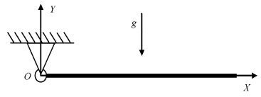
考虑如图3所示柔性单摆,令单摆只在重力作用下自由下落. 此时,在系统的势能表达式中要考虑重力势能的影响.
单摆的重力势能可以表示为
|
\[{{V}_{\text{G}}}=-{{g}^{\text{T}}}W\int_{0}^{L}{\rho }Srdx=-{{g}^{\text{T}}}WR\]
|
(45) |
其中,${ g}$是重力加速度列阵,${ W}$为浮动坐标系到惯性坐标系的坐标变换阵,${ g}$,${ W}$,${ R}$可以分别表示为
|
\[g={{[{{g}_{X}},{{g}_{Y}}]}^{\text{T}}}\]
|
(46) |
|
\[W=\left[ \begin{matrix}
\cos \theta & -\sin \theta \\
\sin \theta & \cos \theta \\
\end{matrix} \right]\]
|
(47) |
|
\[R=\int_{0}^{L}{\rho }Srdx\]
|
(48) |
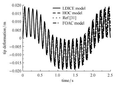
柔性单摆的物理参数同文献[31],$L = 1.8$ m,$S = 2.5\times 10^{-4}$ m$^2$,$I = 1.3\times10^{-9}$ m$^4$,$\rho = 2.766 67\times 10^3$ kg/m$^3$,$E = 68.952$ GPa.
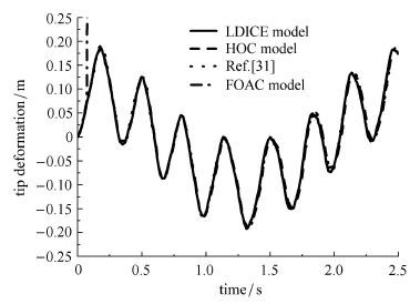
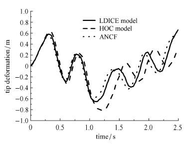
图4为该柔性单摆的末端变形时程曲线,此时变形较小,这几种模型都能很好地吻合. 将弹性模量$E$减小为$6.895 2$ GPa时,由图5可看出一次近似耦合模型的计算结果迅速发散,而本文所用的其他两种耦合模型的计算结果都能与文献[31]中绝对节点坐标法的结果较好地吻合.
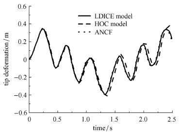
为了说明精确曲率对大变形梁的影响,将曲率纵向变形效应模型、高次耦合模型与绝对节点坐标法(ANCF)模型进行对比研究.再次将柔性梁的材料弹性模量$E$减半至$3.447 6$ GPa,在该弹性模量下,单摆的柔性变得很大,在重力作用下,单摆出现了比较大的变形.图6即为柔性单摆在重力作用下的末端变形时程曲线. 在整个下落过程中柔性梁最大变形达到了0.46 m.高次耦合模型开始出现偏差,但曲率纵向变形效应模型和ANCF模型吻合得很好.
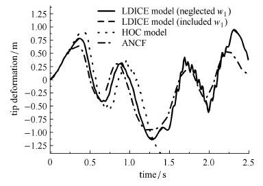
继续将柔性梁的材料弹性模量减小为原始的1/40,即$E = 1.723 8$ GPa,在该弹性模量下,单摆的柔性进一步变大,在重力作用下,单摆将出现更大的变形,最大变形为0.8 m,如图7. 高次耦合模型明显开始偏离ANCF模型,而曲率纵向变形效应模型和ANCF模型还是吻合较好.再将柔性梁的材料弹性模量减小为原始的1/60,即$E = 1.149 2$ GPa,在该弹性模量下,单摆的柔性变形变得更大.如图8,高次耦合模型开始发散,而曲率纵向变形效应模型和ANCF模型的趋势还是比较接近,这说明本文获得的曲率纵向变形效应模型比现有文献中的高次耦合模型更能处理大变形问题.本文提出的曲率纵向变形效应模型是在高次模型基础上多了两部分,一部分是式(35)中的三划线项,由(21)式中的单下划线产生,另一部分是式(35)中的四划线项,由(21)式中的双下划线产生.图8中,曲率纵向变形效应模型分别给出了忽略$w_{1}$ (不考虑式(35)中的四划线项)和考虑$w_{1}$ (考虑式(35)中的四划线项)的两种情形,它们几乎重合在一起.说明曲率纵向变形效应模型中轴向拉压变形量$w_{1}$对弯曲变形能的影响式(35)中的四划线轴项)非常小,为了提高计算效率,可以将其忽略. 但对于式(35)中的三划线项(由非线性耦合变形量产生),在大变形情况下不能忽略,忽略该项就是高次耦合模型,结果如图8所示高次耦合模型发散.
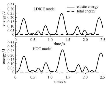
图9为柔性单摆的能量变化曲线,曲率纵向变形效应模型和高次耦合模型的变形能形态相同,系统的总能量始终保持不变(为0),说明数值仿真过程是正确的.
3 结论
本文基于精确曲率公式,在计算柔性梁的弯曲变形能时,考虑柔性梁的纵向变形效应的影响,从而获得了较传统弯曲变形能公式更为精确的柔性梁弯曲变形能计算式. 本文建立的考虑曲率纵向变形效应的刚柔耦合动力学模型,不仅能适用于柔性梁的小变形问题,也能适用于柔性梁的大变形问题,较现有一次近似耦合模型和高次耦合模型在处理柔性梁大变形问题上能力更强.通过与绝对节点坐标法在处理柔性梁大变形问题上的对比验证了曲率纵向变形效应模型的有效性.同时,研究也发现,当轴向拉压变形量($w_{1})$较小时,由于纵向变形($u_{1})$主要由非线性耦合变形量($w_{c})$主导,此时轴向拉压变形量对弯曲变形能的影响不明显,从而为了提高计算效率,曲率纵向变形效应模型中可以忽略轴向拉压变形量$w_{1}$的影响.
参考文献
| [1] |
Likins PW. Finite element appendage equations for hybrid coordinate dynamic analysis. Journal of Solids and Structures, 1972, 8:790-831 |
| [2] |
Kane TR, Ryan RR, Banerjee AK. Dynamics of a cantilever beam attached to a moving base. Journal of Guidance, Control and Dynamics,1987, 10(2): 139-150 |
| [3] |
Wallrapp O, Schwertassek R. Representation of geometric stiffening in multi-body system simulation. International Journal for Numerical Methods in Engineering, 1991, 32: 1833-1850 |
| [4] |
Bakr EM, Shabana AA. Geometrically nonlinear analysis of multibody system. Computer and Structures, 1986, 23(6): 739-751 |
| [5] |
Wu SC, Haug E. Geometric non-linear substructuring for dynamics of flexible mechanical systems. International Journal for Numerical Methods in Engineering, 1988, 26: 2211-2226 |
| [6] |
Wallrapp O, Schwertassek R. Representation of geometric stiffening in multi-body system simulation. International Journal for Numerical Methods in Engineering, 1991, 32: 1833-1850 |
| [7] |
洪嘉振,尤超蓝. 刚柔耦合系统动力学研究进展. 动力学与控制学报,2004,2(2): 1-6 (Hong Jiazhen, You Chaolan. Advances in dynamics of rigid-flexible coupling system. Journal of Dynamics and Control, 2004, 2(2): 1-6 (in Chinese)) |
| [8] |
Liu JY, Hong JZ. Geometric stiffening effect on rigid-flexible coupling dynamic of an elastic beam. Journal of Sound and Vibration,2004, 278: 1147-1162 |
| [9] |
蔡国平,洪嘉振. 旋转运动柔性梁的假设模态方法研究. 力学学报,2005,37(1): 48-56 (Cai Guoping, Hong Jiazhen. Assumed mode method of a rotating flexible beam. Chinese Journal of Theoretical and Applied Mechanics, 2005, 37(1): 48-56 (in Chinese)) |
| [10] |
章定国,余纪邦. 作大范围运动的柔性梁的动力学分析. 振动工程学报,2006,19(4): 475-479 (Zhang Dingguo, Yu Jibang. Dynamical analysis of a flexible cantilever beam with large overall motions. Journal of Vibration Engineering, 2006,19(4): 475-479 (in Chinese)) |
| [11] |
刘锦阳,李彬,洪嘉振. 做大范围空间运动柔性梁的刚-柔耦合动力学. 力学学报,2006,38(2): 276-282 (Liu Jinyang, Li Bin, Hong Jiazhen. Rigid-flexible coupling dynamics of a flexible beam with three-dimensional large overall motion. Chinese Journal of Theoretical and Applied Mechanics, 2006, 38(2): 276-282 (in Chinese)) |
| [12] |
邓峰岩,和兴锁,李亮等. 耦合变形对大范围运动柔性梁动力学建模的影响. 计算力学学报,2006,23(5): 599-606 (Deng Fengyan, He Xingsuo, Li Liang, et al. Dynamics modeling of the elastic beam undergoing large overall motion considering coupling effect in deformation. Chinese Journal of Computational Mechanics, 2006,23(5): 599-606 (in Chinese)) |
| [13] |
和兴锁,邓峰岩,王睿. 具有大范围运动和非线性变形的空间柔性梁的精确动力学建模. 物理学报,2010,59(3): 1428-1436 (He Xingsuo, Deng Fengyan, Wang Rui. Exact dynamic modeling of a spatial flexible beam with large overall motion and nonlinear deformation. Acta Physica Sinica, 2010, 59(3): 1428-1436 (in Chinese)) |
| [14] |
吴胜宝,章定国. 大范围运动刚体-柔性梁刚柔耦合动力学分析. 振动工程学报,2011,24(1): 1-7 (Wu Shengbao, Zhang Dingguo. Rigid-flexible coupling dynamic analysis of hub-flexible beam with large overall motion. Journal of Vibration Engineering, 2011, 24(1):1-7 (in Chinese)) |
| [15] |
陈思佳,章定国. 中心刚体-变截面梁系统的动力学特性研究. 力学学报,2011,43(4): 790-794 (Chen Sijia, Zhang Dingguo. Dynamics of hub-variable section beam systems. Chinese Journal of Theoretical and Applied Mechanics, 2011, 43(4): 790-794 (in Chinese)) |
| [16] |
方建士,章定国. 旋转悬臂梁的刚柔耦合动力学建模与频率分析. 计算力学学报,2012,29(3): 333-339 (Fang Jianshi, Zhang Dingguo. Rigid-flexible coupling dynamic modeling and frequency analysis of a rotating cantilever beam. Chinese Journal of Computational Mechanics, 2012, 29(3): 333-339 (in Chinese)) |
| [17] |
Shabana AA. An absolute nodal coordinate formulation for the large rotation and deformation analysis of flexible bodies. Technical Report. no. MBS96-1-UIC, 1996 |
| [18] |
Berzeri M, Shabana AA. Development of simple models for the elastic forces in the absolute nodal co-ordinate formulation. Journal of Sound and Vibration, 2000, 235(4): 539-565 |
| [19] |
Berzeri M, Shabana AA. Study of the centrifugal stiffening effect using the finite element absolute nodal coordinate formulation. Multibody System Dynamics, 2002, 7: 357-387 |
| [20] |
Omar MA, Shabana AA. A two-dimensional shear deformable beam for large rotation and deformation problems. Journal of Sound and Vibration, 2001, 243(3): 565-576 |
| [21] |
Shabana AA, Mikkola AM. Use of the finite element absolute nodal coordinate formulation in modeling slope discontinuity. Transactions of the ASME, Journal of Mechanical Design, 2003, 125: 342-350 |
| [22] |
Yoo HH, Kim JM, Chung J. Equilibrium and modal analyses of rotating multibeam structures employing multiple reference frames. Journal of Sound and Vibration, 2007, 302: 789-805 |
| [23] |
Gerstmayr J, Irschik H. On the correct representation of bending and axial deformation in the absolute nodal coordinate formulation with an elastic line approach. Journal of Sound and Vibration, 2008,318(3): 461-487 |
| [24] |
Liu C, Tian Q, Hu HY. New spatial curved beam and cylindrical shell elements of gradient-deficient absolute nodal coordinate formulation. Nonlinear Dynamics, 2012, 70(3): 1903-1918 |
| [25] |
Liu JY, Hong JZ. Geometric stiffening effect on rigid-flexible coupling dynamic of an elastic beam. Journal of Sound and Vibration,2004, 278: 1147-1162 |
| [26] |
Liu ZY, Hong JH, Liu JY. Complete geometric nonlinear formulation for rigid-flexible coupling dynamics. Journal of Central South University of Technology, 2009, 16: 119-124 |
| [27] |
陈思佳,章定国,洪嘉振. 大变形旋转柔性梁的一种高次刚柔耦合动力学模型. 力学学报,2013,45(2): 251-256 (Chen Sijia, Zhang Dingguo, Hong Jiazhen. A high-order rigid-flexible coupling model of a rotating flexible beam under large deformation. Chinese Journal of Theoretical and Applied Mechanics, 2013, 45(2): 251-256 (in Chinese)) |
| [28] |
范纪华,章定国. 旋转悬臂梁动力学的B 样条差值方法. 机械工程学报,2012,48(23): 59-64 (Fan Jihua, Zhang Dingguo. Bspline interpolation method for the dynamics of rotating cantilever beam. Journal of Mechanical Engineering , 2012, 48(23): 59-64 (in Chinese)) |
| [29] |
范纪华,章定国. 旋转柔性悬臂梁动力学的Bezier 插值离散方法研究. 物理学报,2014,63(15): 154501 (Fan Jihua, Zhang Dingguo. Bezier interpolation method for the dynamics of rotating flexible cantilever beam. Acta Physica Sinica, 2014, 63(15): 154501 (in Chinese)) |
| [30] |
杜超凡,章定国,洪嘉振. 径向基点插值法在旋转柔性梁动力学中的应用. 力学学报,2015,47(2): 279-88 (Du Chaofan, Zhang Dingguo, Hong Jiazhen. A meshfree method based on radial point interpolation method for the dynamic analysis of rotating flexible beams. Chinese Journal of Theoretical and Applied Mechanics,2015, 47(2): 279-288 (in Chinese)) |
| [31] |
李彬,刘锦阳. 大变形柔性梁系统的绝对坐标方法. 上海交通大学学报,2005,39(5): 827-831 (Li Bin, Liu Jingyang. Application of absolute nodal coordination formulation in flexible beams with large deformation. Journal of Shanghai Jiaotong University, 2005,39(5): 827-831 (in Chinese)) |
RIGID-FLEXIBLE COUPLING DYNAMIC MODELING AND SIMULATION WITH THE LONGITUDINAL DEFORMATION INDUCED CURVATURE EFFECT FOR A ROTATING FLEXIBLE BEAM UNDER LARGE DEFORMATION
Zhang Xiaoshun, Zhang Dingguo , Hong Jiazheny
1. School of Sciences, Nanjing University of Science and Technology, Nanjing 210094, China;
2. Department of Engineering Mechanics, Shanghai Jiaotong University, Shanghai 200240, China
Abstract: The dynamics of a flexible beam which is rotating in a plane is further studied in this paper. The dynamic model of the rigid-flexible coupling system under large deformation is established and here by the dynamic simulation is also carried out. In this dynamic model not only the transversal bending deformation and the longitudinal deformation (including the axial stretching deformation and the longitudinal shortening term caused by the transversal bending deformation) of the flexible beam are considered, but also the curvature e ect induced by the longitudinal deformation is included. In the previous studies the bending deformation energy of the beam is usually expressed in terms of the bending deformation directly without considering the longitudinal deformation e ect. To take into account the influence due to the longitudinal deformation on the bending deformation energy of the beam the precise curvature formula in the form of parametric equation expressed in the floating frame of reference is used to calculate the bending deformation energy. And consequently the rigid-flexible coupling dynamic model of the system with the said the longitudinal deformation induced curvature e ect (LDICE) model is obtained. To validate the algorithm presented in this paper, several dynamic simulation examples are given. The results show that the dynamic model presented in this paper can not only be used in the analysis of the small deformation dynamics, but also in the large deformation dynamics, and indicate that the dynamic model with the curvature e ect obtained in this paper is more suitable to solve for the large deformation dynamic problems than the high-order coupled (HOC) model presented in the existing literature. The results obtained using the proposed model are compared with the results obtained using the absolute nodal coordinate formulation (ANCF) which is suitable for large deformation problems, and consequently validate the dynamic model proposed in this paper.
Key words:
flexible beam rigid-flexible coupling dynamics large deformation longitudinal deformation induced curvature effect


 2016, Vol. 48